This thread has been locked.

If you have a related question, please click the "Ask a related question" button in the top right corner. The newly created question will be automatically linked to this question.

UCC256303: Skipping pulses

Part Number: UCC256303
Other Parts Discussed in Thread: UCC256403

We are following the guidelines in SLUA582A for tuning the feedback loop.

As suggested, we modified the bulk voltage resistors to start the application at an input voltage low enough to keep output voltage out of regulation (at about 75V instead of 85V) and  force converter to work around maximum gain. However, we observed that the switching frequency suddenly changes and converter intermittently skips some pulses. At fixed load and input voltage, I would expect minimal variation of switching frequency. Situation get worse at higher input voltage.

Some examples in the following scope acquisitions.
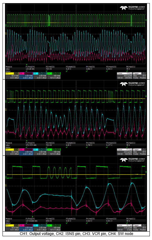
  

What might be the cause of this kind of instability? Or what would you suggest to investigate?

At nominal voltage, converter always works in burst mode and is then unable to regulate output voltage. Again, I would not expect burst mode when output voltage is well below regulation value.

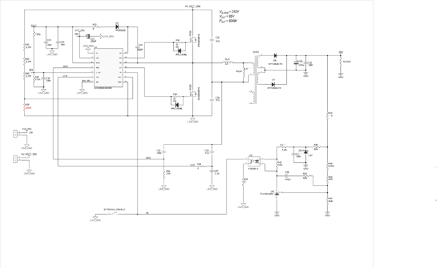
Application specs and schematic attached. 
Regards

  • Hi 

    It seems like the Vcr is unstable , so controller will operate to burst mode during Vcr drop.

    you can fine tune the feedback loop compensator to let Vcr stable , or you can change the controller to UCC256403 , it is the next gen of UCC256303 , and it can add the burst hysteresis.

    you can refer the application note as below to use UCC256403

    https://www.ti.com/lit/pdf/slua966

  • Thanks for your quick reply.

    Unfortunately, it is very difficult to obtain UCC256403 due to shortage of components on main distributor. So, migrating to new version of IC does not look like a viable option.

    Are you saying that VCR pin is unstable due to the compensation loop on FB pin? We were unable to get loop measurements and then fine tune the feedback loop due to the instability shown in my previous post. Could you suggest other way to improve the feedback compensation?

    Or are you referring to the capacitor voltage divider on VCR pin? What else can be done to make VCR pin more stable?

    Are there other signals that could wrongly trigger burst mode?

  • the schematic in the picture is not clear , so I'm not sure the parameter using now.

    the Vcr feedback loop like peak current mode , the Vcr voltage is the current signal , and the FB current is the threshold of peak current mode , so the Vcr pin amplitude is controlled by FB current pin.

    you can try to increase the resistance which series with optocoupler at secondary side. 

  • Sorry, here's a better picture. I hope the schematic is clear enough now.

    We will try different resistor values, as per your suggestion.
    Regards

  • After modifying both the capacitor divider on resonant voltage and some values of compensation network, VCR pin seems more stable.

    However, the converter is still working in burst mode also when heavily loaded (at about 400W). Some examples in start-up waveforms below.

    Could you help us why the controller is unable to get out of burst mode? Is there something else we are overlooking?

    We tried to remove upper resistor on LL/SS pin to set minimum BMT threshold and follow procedure to set it as described in the application note, but that behaviour did not change.

  • Hi 

    the burst mode setting also impacted by Vcr & LL/SS , the burst mode operation still like peak current mode that Vcr is the current sense signal and LL/SS set the threshold, but IC still has offset at internal LL/SS threshold,

    It still has risk to operate at burst mode even you don't add the resistor divider , if you set the Vcr signal too small.

    You can reduce the Vcr low side capacitor divider capacitance then Vcr voltage would be increased and out of burst mode.