This thread has been locked.

If you have a related question, please click the "Ask a related question" button in the top right corner. The newly created question will be automatically linked to this question.

TPS65218: In system programming

Part Number: TPS65218
Other Parts Discussed in Thread: , , , , TPS65910, TPS650250, TPS65217, IPG-UI, USB2ANY

I am designing a  board with the Am335x and the TPS65218xx. It is pretty bare bones so I don't need RTC, DCDC5 or DCDC6, but I am running the Am335x at 1Ghz. With the semiconductor shortage, it is hard to find TPS65218D0 or TPS6521815 parts. I can find TPS6521825 parts. I would like to completely assemble boards with the TPS65218xx installed and program them in system. I need to ensure that the regulator outputs (VDCDC1-VDCDC4, VLDO1) are not enabled but I can access the I2C port and write to the EEPROM.  I have a BOOSTXL-TPS65218 programmer/eval board and have not been able to find a combination of control inputs to do what I want to do. If I set PWR_EN switch to 0 and press the PB, I can access the I2C port but I can't write to the EEPROM. What do you recommend for in system programming of any type of TPS65218xx parts?

  • Additional note: If the PWR_EN switch technique had worked, I would have used a pull up resistor to 5V to PWR_EN on the board with a jumper to ground to do the in system programming.   A 3-pin connector  for the I2C and ground pins to the BOOSTXL programmer.

  • Hi Burt,

    Thanks for reaching out! Which registers are you interested in re-programming on the TPS6521825

    The TPS65218x is one of our user programmable PMICs and it allows the user to re-program several registers using the booster pack or with the device soldered in the system as long as there is I2C communication. However, even though you can change the register settings, not all of the changes can be saved into the EEPROM. Only the register bits that have "E2" in the "Type" column of the register map can be saved into the EEPROM so they can become the new power-up default settings. Just for your reference, the ENABLE registers do not have "E2" bits.

    Here is the link to the datasheet (register map starting on page 51)

    Thanks,

    Brenda

  • Hi Brenda,

    Thanks for responding. I really only need to change the DCDC and LDO voltage levels and the sequencing of the DCDC and LDO voltage outputs. Because I may be reprogramming a TPS6521825, which is for an iMX processor, to power a 1Ghz Am335x processor, I  need the PMIC to power up with no voltage outputs so I can program and save to EEPROM before enabling the voltage outputs. I found that using PWR_EN input doesn't work as it doesn't allow me to write to the EEPROM.

  • Hi Burt,

    Thanks for providing that information. The good news is that all registers that you would need to update to make the changes on the rails output voltages and sequencing have E2 bits that can be re-programed and saved into the EEPROM. However, the PWR_EN signal would need to be high otherwise the PMIC will fall info the OFF state where I2C is not available. Here are my recommendations:

    • For prototype, I recommend re-programming the PMIC using the booster pack before soldering it into the actual system. Please keep in mind that after making the changes a consecutive write of 0x50, 0x1A, 0xCE needs to be send to the password register to commit the current register settings
      to EEPROM memory so they become the new power-up default values. Let me know if you run into any issues.
    • For production programming services, you can get in contact with Arrow (TI partnered distributor) and they will guide you through the process and information needed to support a custom NVM config. Here is the link: Arrow programming services
    • As an alternative solution, we are also promoting TPS650250 to power the AM335x processor. I will include some useful links below to help you get familiar with this PMIC. Let me know if you have any questions.

    TPS650250 Datasheet

    AM335x PMIC Selection Guide (Rev. A)

    Powering the AM335x With the TPS650250 (Rev. B)

    Thanks,

    Brenda

  • Hi Brenda,

    The Modes of Operation flow chart, section 8.3.1 of the TPS65218 data sheet, shows that during the WAIT_PWR_En state I2C is available yet the PWR_En signal is low. This state is only on for 20 seconds before exiting. I have verified that I can get into this state by depressing the PB and access the I2C port and write to it with IPGUI and the BOOSTER pack as I get the green feedback messages. But when I try to write to the EEPROM by writing the 3 PASSWORD values, I get a red feedback error message.  This all occurs within the 20seconds after I depress the PB. This indicates that in the WAIT_PWR_EN state I can access the I2C but can't write to the EEPROM. Is this true?

    I would like to disable the DCDC1:4 and LDO1 outputs with a jumper wihout disabling the I2C and EEPROM writes so I can attach the BOOSTER pack and reprogram the TPS65218 without powering the Am335x CPU. I have tried the above technique without success. Is there a way to do this?

    I have looked at other PMICs for the Am335x and the only one to support 1Ghz and is available today, and in the near future, is the TPS65218. The TPS650250 doesn't have enough current outputs for my application. The TPS65910 is out-of-stock. TheTPS65216 is out of stock. The TPS65217 doesn't have enough high current outputs and is out-of-stock.

  • Hi Burt,

    Disabling the rails with a jumper without making the changes through I2C/ENABLE register is a scenario we haven't validate. I recommend re-programming the EEPROM when the PMIC is stable and in "Active" state. Just for your reference, I replicated that you were trying to do and re-programmed one of the rails output voltage (DCDC1) within the 20s when the PMIC was in "WAIT_PWR_EN". I was able to do so and didn't see any issues. Here are the steps I followed using the booster pack and IPG_UI within 20s after powering up the device:

    1. powered on the booster pack with the PWR_EN pin low (S2 switch in the board).
    2. went to the DCDC1 register (0x16) and moved the slider on the right side to select a different output voltage. 
    3. then I clicked on "W" to write the new settings 
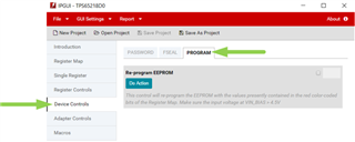
    4. went to the "Device Controls" (left side of the GUI) and selected the "Program" tab to click on "Do Action" which automatically writes the consecutive sequence to the password register.

    Please keep in mind that our GUI comes with some built in features that allows customers to re-program the devices fast and easy. If the GUI is not used then all the required I2C commands must be manually executed to make changes. For example, registers to change the output voltages are password protected (see section 5.6.1 "Password Protection" in the spec). These would require to write the address of the destination register XORed with the protection password (0x7Dh) to the password register. Then, you can write the data to the password protected register (i.e. DCDC1). Then you need to change "GO" or "GODSBL" bit in register 0x1A. The last step would be to send the three commands to the passwords register to save the new settings into the EEPROM. Please let me know if you try this and run into issues. 

    Thanks,

    Brenda

  • Hi Brenda,

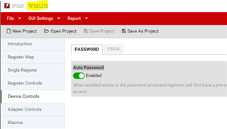
    Maybe part of my problem is my IPG-UI is not the same as yours. In my "Device Controls" section I do not have a "Program" tab. My IPG-UI version is 2.5.0.5. The "Device Controls" section only has Password and FSeal tabs. How do get the same IPG-UI as yours which has the "Program" tab?

  • Hi Burt,

    This is very strange. Did you download the IPG-UI along with BOOSTXL-TPS65218 IPG-UI Device Support File? Here are the options I have in the "Device Controls" section:

    Thanks,

    Brenda

  • Hi Brenda,

    I did download BOOSTXL-TPS65218 IPG-UI Device Support File/slvc750 and execute it without any improvements. My USB2ANY  version is 2.7.0.0.

  • Hi Burt,

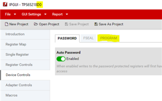
    I think I found the issue. It should be independent from the USB2ANY version. Once you open the IPG-UI, go to "Select Device" and make sure you select the 1.2 version "TPS65218-1.2"  from the drop down menu. You are probably using the 1.1 version which doesn't include the program tab feature. Here are the differences:  

    Device: TPS65218-1.1

    Device: TPS65218-1.2

    Thanks,

    Brenda

  • Hi Brenda,

    Thank you, using the 1.2 version did fix the "PROGRAM" tab problem. I had saved the project while using the 1.1 version and it overrode the 1.2 version so I had to resave after selecting the 1.2 version.

    Unfortunately, I missed the point in the flowchart which shows that the DCDC1-4 outputs are enabled even when the PB is pushed, so while I can reprogram the EEPROM, the old voltage values and sequencing are still active and will damage my CPU. I need to find another way to reprogram in system without enabling the DCDC1-4 outputs.

    Thanks again.