This thread has been locked.

If you have a related question, please click the "Ask a related question" button in the top right corner. The newly created question will be automatically linked to this question.

USB-TO-GPIO: Proper I2C Syntax

Part Number: USB-TO-GPIO

Hello,

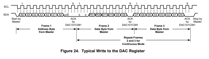
I'm trying to understand the syntax from the manual correctly. I'm trying to transmit some information to a DAC in the format below.

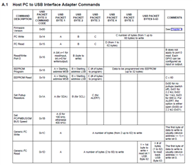
As you can see, the data I'm trying to transmit is 14 bits separated into two bytes. I'm trying to transmit 0x26C to the device address 0x0E. Looking at the reference guide for the USB-TO-GPIO and the interface below:

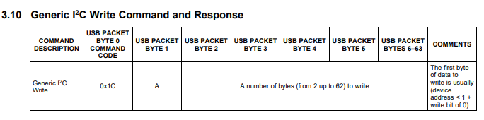
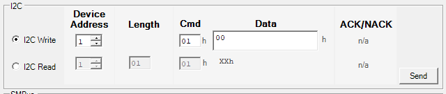
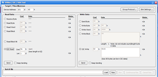
I'm trying to understand the proper way to format this. Device address is simple enough, just being 14. For data, I'm a little confused on the format, since it's a 14-bit transmission separated into two bytes. Would it be best to separate these into bytes, 0x02 and 0x6C, or can the program handle leaving the data as 0x26C (0x02 and 0x6C combined)? Essentially, what I'm asking is do I have to make two separate writes or will the program handle that for me? Lastly I'm confused on the "Cmd" entry. I'm simply looking at section 3.10, "Generic I2C Write Command and Response" as attached, would the Cmd field be 1C?

  • Hi, Collin,

    I am not sure what GUI you are using. If you use Fusion Digital Power Designer -> SMBus/I2C/SAA tool, then the GUI use "I2C Read/Write", not "I2C Generic Read/Write" protocol

    Byte0        | Byte1                           | Byte2 | Byte3 | Byte4 | Byte5  |…………………..

    USB code |  A                                  |  B      | C        | C number of bytes (1 to 60 bytes)

     0x14         | (Slave Addr )<< 1 or 0 | Cmd  | Len    | C data bytes


    From the below screenshot info, GUI will send the below data to USB adapter

    byte0 | byte1 | byte2 | byte 3| byte4 | byte5 | byte6 | byte7 | …….[byte

    0x14    0xCA   0xA0   0x02    0x01    0xD1  | 0x02  | 0x00  | 0x00 | 0x00 |.....

    where:

    slave address = (0x65 << 1) | 0 = 0xCA

    USB code = I2C Write = 0x14

    Cmd = 0xA0

    Data = 2 bytes of data: 0xD102

    Anne Ngo

    Texas Instruments

  • Hi Anne,

    Thank you for the help. I've installed Fusion Digital Power Designer and that seems to be working with Windows 10. I'm still running into some issues particularly with the Cmd byte. As you can see below, the writing procedure to my DAC is simply Byte 1: Address, Byte 2: Data1, and Byte 3: Data2. 

    So I'm a little confused on what to do with the command byte since the procedure states that the byte immediately after the address byte is simply the first line of data. I've tried leaving it as 0x00, but again I receive a NACK. I've also tried setting Cmd to the first Data byte, but to no avail. Is there anyway to simply send those data bytes without any cmd?

    Thank you,

    Colin Hice

  • Hi, Collin,

    Sorry that currently Fusion GUI does not support I2C Generic Read/Write. You can reach out to the owner of the GUI that you used before to see if that GUI support I2C Generic Read/Write.

    The 0x14 is USB adapter command code so that USB adapter will know how to parse the data and then re-pack data to send over the bus.

    The "cmd" shown on GUI is slave device's command code. If slave device supports I2C command, it will know what to do once receive this command.

    Anne Ngo

    Texas Instruments