A related question is a question created from another question. When the related question is created, it will be automatically linked to the original question.
If you have a related question, please click the "Ask a related question" button in the top right corner. The newly created question will be automatically linked to this question.
The output current for mode change depends on the input voltage, inductor value, and the programmed switching frequency. At higher programmed switching frequencies, the load at which the mode change occurs is greater. For applications where the switching frequency must be known for a given condition, the transition between PFM and PWM must be carefully tested before the design is finalized.
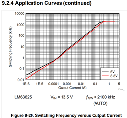
You can find one tested switching frequency curves in datasheet:
When setting at 2.1MHz Auto mode, the break point would be around 300mA under this specific test condition.
You can also use WEBENCH tools to simulate load transient response, in case you have your own design.
For the diagram, we can see the threshold Iout between FPWM and PFM is 0.3A. But in my customer measurement, the threshold is 1.3A.
If my customer add one more 10uF in output side, the Iout threshold between FPWM and FPM should be 0.3A. It's weird to me because I think the threshold should be related to internal chip current like ripple current.
For this device, inductor peak current min= 650mA, when iL-peak<650mA, the device will change to PFM mode. Since Iripple=(Vin-Vo)*D/L*fsw, it has no relationship with output capacitor. Please ask your customer to capture the waveform of SW pin w/ and w/o the extra capacitor, and send to us for review.