This thread has been locked.

If you have a related question, please click the "Ask a related question" button in the top right corner. The newly created question will be automatically linked to this question.

LM5146: Request about CC circuit of LM5146

Part Number: LM5146
Other Parts Discussed in Thread: LM5117, LMV431, LM25085, INA180, LM5145

Hi

My customer implemented the cc/cv circuit as a circuit of the finger1 of the snva829 document.
(Buck ic: lm5146)

https://www.ti.com/lit/an/snva829/snva829.pdf?ts=1634188748088&ref_url=https%253A%252F%252Fwww.google.com%252F

If you give me your email address, I'll send the overall SCH . MY customer asked for security.


My customer  wants to meet the following conditions. Is it possible to realize this circuit?
I said no, but my customer wants a detailed explanation. Tell me if you can implement the contents below.

-condition-
load: general electronic load
Raise the output load from 0A.
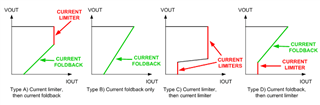
When the output load rises, the set voltage 14v is maintained.(CV)
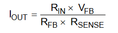
When the output current exceeds the set current 14A, the current is maintained at 14A and the output voltage is lowered.(CC)

Thanks

  • Hi DAvid,

    Yes, that is conventional CC/CV operation, otherwise known as brickwall current limit.

    Please use the LM5146 quickstart calculator to check component values for a 14A design. Set the normal current limit above that, like 20A, so that the CC circuit always engages first.

    Regards,

    Tim

  • By the way, if a 65V input rating is sufficient, you can consider the LM5117 that has a CM pin that simplifies CC/CV implementation.

  • Hi Timothy

    Unfortunately, LM5117 cannot be used because the input voltage is up to 100V.

    Additional questions

    Like the SCH, is it okay to set CV on the FB pin of LM5146 and add CC circuit?

    However, when R6 and R7 of FB are connected, the calculated current value does not come out.

    And even if the current limit of LM5146 is 20A or more, the brick wall current limit does not operate.

    Can you review SCH?

    I'll send the SCH personally at the request of the customer.

    Can you tell me your email address?

    Thanks

  • Hi David,

    Yes, you can setup CV operation just like a normal regulator design using the FB pin and then add the peripheral CC circuit that engages at a certain level.

    I'll take a look at the schematic. I'll send my email via friend on e2e. In the meatime, please complete and send the LM514 quickstart calculator for this CV circuit. Enter the derated vlaue for ceramic output cap (with voltage) and use the compensation values recommended in the file. in particular, check the RC lead network across the upper FB resistor.

    Regards,

    Tim

  • Hi

    I send the file in a private message, but there is no answer.
    Please check it.

    Thanks

  • Thanks, David. I will get back to you via chat.

  • Hi Timothy

    The CC operation of the designed board seems to be done.

    Referring to P.2 in the document snva829, the cc current was calculated as 14.27A and designed.

    However, the voltage drops from more than 3A.

    In relation to this, the waveform are as follows.

    What is the reason for not operating CC according to the calculated current (14.27A)?

    Additionally, please review the circuit I requested before.


    -Waveform-

    Ch1(Yellow):TR(Q7) Base Voltage

    Ch2(Blue):TR(Q7) Emitter Voltage

    Ch3(Red):Output Current

    Ch4(Green):Output Voltage

    Math1(Orange):TR(Q7) Base-Emitter Voltage

       <Output Current 3A>

     <Output Current 5A)

     <Output Current 10A)

    Thanks

  • Hi David,

    Recommendation is to verify the circuit first in CV mode and then add the CC circuit. If the CC circuit is pulling on FB at 3A, you can check the circuit nodes to analyze the circuit behavior.

    Here is the applicable expression (from Equation 1 in app note SNVA829):

    where RFB is the parallel combination of the upper and lower FB resistors.

    Regards,

    Tim

  • Hi Timothy

    "where RFB is the parallel combination of the upper and lower FB resistors."

    Does this mean that RFB is good for parallel combination? RFB is the resistance below, right?

    Thanks

  • Yes, RFB represents the equivalent FB resistance in that schematic. Use the parallel resistance value for your calculations of the CC mode setpoint.

    --

    Tim

  • Hi

    Thanks for your support.

    However, customers do not yet have the desired CC performance.

    How is it good to debugging to achieve the desired brickwall current limit 14A?

    If it helps solve the problem, I will send you a waveform. What kind of waveform do you need?

    As advised, it does not work, so I ask for help.

    Thanks

  • Hi David,

    Is the circuit working correctly at a certain CC current level? If so, just adjust the setpoint as needed.

    Here are some steps:

    1. Disconnect the CC circuit (e.g. lift the NPN transistor) and verify the circuit runs in CV mode up to ~20A (the current limit setpoint must be set above the CC setpoint).
    2. Remove the connection to the FB pin of the IC from the CC circuit and place the same Thevenin feedback resistance to GND. Then check that the CC circuit is engaging at the correct output current.
    3. Finally, connect the CC circuit to the CV circuit and verify they are both operating correctly as expected. Note that it is important to keep the FB trace as short as possible to minimize noise. The lower FB resistor should be located at the FB and AGND pins.

    Regards,

    Tim

  • Hi

    I took the test like a guide, but it didn't go well.

    How should the CC circuit work?(CC Current :14A)
    In the current state, when the current gradually rises and reaches the calculated 14A, the VFB voltage slowly rises to 0.8V.

    ex)Vfb= 0V.0.1V.0.2V...0.8V

    Is this right?

    If the VFB rises slowly, it affects the stage FB before reaching the CC current, so the CV does not maintain up to 14 A and the voltage drops slowly from the beginning.

    If TR(Q7) is closed until it reaches 14A and reaches 14A, shouldn't it be changed to CC by opening the TR and affecting FB?

    Thanks

  • Hi David,

    In the circuit recommended in app note SNVA829, the zener from VOUT to FB sets the CV setpoint. The CC circuit engages based on the equation 1 here:

    Regards,

    Tim

  • Hi

    Of course, the CV was set and tested with the Zener diode.

    However, the output voltage starts to drop from about 2A. (set cc current 14A)

    I think the operation of the cc circuit is wrong. Is it right to move like the below?

    ------------------------------------------------------------------------------------------------------------------


    How should the CC circuit work?(CC Current :14A)
    In the current state, when the current gradually rises and reaches the calculated 14A, the VFB voltage slowly rises to 0.8V.

    ex)Vfb= 0V.0.1V.0.2V...0.8V

    Is this right?

    If the VFB rises slowly, it affects the stage FB before reaching the CC current, so the CV does not maintain up to 14 A and the voltage drops slowly from the beginning.

    If TR(Q7) is closed until it reaches 14A and reaches 14A, shouldn't it be changed to CC by opening the TR and affecting FB?

    -------------------------------------------------------------------------------------------------------------------------------------------------------------------------

    Thanks

  • Hi David,

    Upon review of that app note, the first circuit mentioned is really for charging batteries or super caps where current is limited to a certain value while voltage increases (and then finally the zener engages to clamp the voltage and reduce the current). This is obviously not the "CC/CV" behavior you require. You need a circuit with a reference that injects current into FB to reduce VOUT when a certain voltage on the shunt is reached. I will check if we have something for this.

    Regards,

    Tim

  • Take a look at this app note: https://www.ti.com/lit/an/snva486a/snva486a.pdf

    However, the LM25085 controller is different as it has an ISENS pin for current limit that does not engage hiccup. For the LM5146, we need to inject a current into FB to reduce VOUT when the appropriate IOUT is reached. So configure the LMV431 to pullup on FB instead.

    Regards,

    Tim

  • Hi 

    The circuit below was connected to the FB of LM5146.
    But it doesn't work.
    Is this the right way?

    Thanks

  • Hi

    "So configure the LMV431 to pullup on FB instead."

    How do I configure it? Can you show us the picture?

    Thanks

  • Hi David,

    Just put a resistor on the cathode of the '431 and connect to FB through a series diode (so that the CC circuit doesn't interfere with the CV loop by loading FB).

    Note also that you can use an INA180 to amplify the shunt voltage and reference it to GND. Another implementation instead o the '431 might be a reference with an op amp to source current into FB directly and avoid the series diode (we haven't checked this yet, but I will look into it).

    Regards,

    Tim

  • Hello
    I am an Engineer testing the above.

    First of all, the CC circuit does not work even if the circuit is configured as above.

    I would like to ask you two questions.

    1. Is there any way to use I-Limit?

    2. Is there any way to come out like one of the foldback waveforms below?

    Please answer about my questions.

    thank you.

  • Hi Oh,

    The original circuit taken from app note SNVA829 is for battery charging, where CC is maintained as the battery voltage increases. Then the zener engages to clamp the voltage. So it's effectively CC first, then CV.

    The requirement here is different as it requires a brickwall current limit, i.e. CV first, then CC. It's not possible to use the ILIM pin as the controller will enter hiccup mode if there are 128 consecutive clock cycles in current limit. As a result, the external current limit circuit must instead manipulate FB to reduce VOUT when the required current limit is reached. We normally use the LM5117 controller for this function as it has a CM pin. This is the first time I've seen the LM5146 with this requirement. The circuit described above works in simulation, but we have not tested it on the bench yet. I can share the SIMPLIS model if needed.

    Regards,

    Tim

  • Hello 

    If so, can I share the simplis model to use for review?

    Tahnk you.

  • Hi Oh,

    Here is the file, please edit as needed.

    Regards,

    Tim

    VMC brickwall OCP r2.sxsch

  • Hello

    As a result of the configuration like the simulation circuit, the output current is not fixed, but the voltage is dropping. Thank you for caring me.

    I have another question. Currently, we are reviewing the IC heating issue.

    I configured the VCC according to the data sheet capture. When there is no load, there is a time delay in reaching the set voltage.

    The voltage applied to VCC through the diode is about 13.8V. Can you confirm the reason for the time delay?

    please answer about my question.

  • Hi Oh,

    Can you confirm where the time delay is occurring - please send a waveform if possible. If VOUT drives VCC, then VCC should rise as soon as Vout exceeds 7.5V (the nominal VCC level) plus a diode drop.

    Note that 13.8V is really high on VCC, close to the 14V max. Consider putting an extra diode in series to reduce the voltage. This will also reduce FET gate drive losses.

    Regards,

    Tim

  • Hello

    We will capture the waveform and reply to you.
    What is the proper VCC input voltage?

    And I have one more question. Is there any additional way to lower the heat on the IC and FET side? Please suggest.

    thank you.

  • If your output is 14V, use two standard diodes (not Schottky) in series -- that should give you ~12.6V at VCC with some margin during load transients, etc.

    In terms of heat spreading, it's mainly down to FET and inductor selection as well as PCB layout. Take a look at the LM5145 5V/20A EVM. Also, send a completed quickstart calculator so we can review losses.

    Regards,

    Tim