This thread has been locked.

If you have a related question, please click the "Ask a related question" button in the top right corner. The newly created question will be automatically linked to this question.

BQ25505: Limiting charging current to battery at high temperature

Part Number: BQ25505
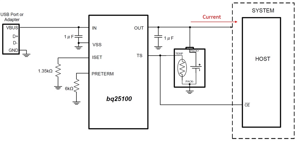
Other Parts Discussed in Thread: BQ25100

Hi, 

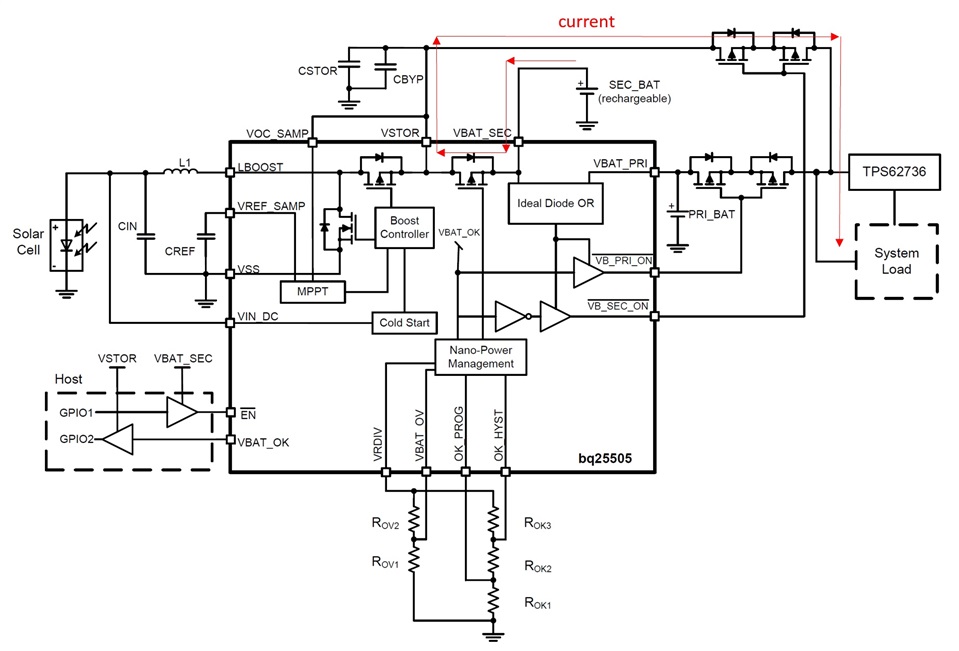
I am using BQ25505 to charge my 4V battery using a solar cell. Solar cell will input about 90mW at 1 SUN

My VBAT_OK=3V, so battery current can raise to 30mA. My battery maximum charging current spec is 100mA @-20-50° and 20mA@-40-65°. Boost charger seems to exceed maximum charging current of battery (20mA) @ 1SUN and 50-65° temperature range. 

How can I limit charging current @50-65° to 20mA max to prevent damaging battery? Can it be done through BQ25505 directly, and if not, what could be the best external circuitry to add (with minimal power waist) to perform this functionality. 

  • Hi Mohammed,

    With 90mW input and max efficiency of 90%, the boost charger max output is 90mW*90% = 81mW then device by 4V = 20.25mA but you are correct at lower battery voltages, the charge current could be higher.  Keep in mind the charge current comes in pulses not DC so it will be less than the calculations.

    The most robust way would be to increase the BQ25505 VSTOR=VBAT_SEC slightly above 4V and place a linear regulator like BQ25100L following it.  The BQ25100L allows you to set max charge current and has TS function to stop charge at high temp.

    A more crude option would be to add a series resistor between the BQ25505 and the battery.  The resistor would drop some power and limit the current into the battery.  

    Regards,

    Jeff

  • Thanks Jeff, 

    You mentioned the charging current comes in pulses. What is the amplitude, frequency and duty cycle of these pulses in my case? 

  • Hi Mohammed, 

    The amplitude, frequency and duty cycle is not easily computed as it is a function of the MPP function and efficiency.  You can see how the IC operates in a couple of the waveforms below.  Blue is the inductor current pulses and pink is VSTOR=VBAT voltage.

    Regards,

    Jeff

  • So you suggest to use BQ25100L between BQ25505 pin VBAT_SEC and battery? 

    There is a confusion because BQ25505 drives the load through an internal FET from the current draw from battery. But in case of using BQ25100L, load is supposed to come after the battery. Can you advise on the suggested architecture. 

  • Hi Mohammed,

    The load comes from VSTOR=VBAT_SEC regardless.  The PFET between VSTOR and VBAT_SEC only turns off to provide battery undervoltage protection when V(BAT_SEC)<2.2V.

    If you are using the MUX feature then you short VSTOR=VBAT_SEC, connect VSTOR_VBAT_SEC to IN of BQ25100, OUT to the battery and the input side of the external MUX FETs.

    Regards,

    Jeff

  • Thanks. We are not using MUX function. 

    So it seems we should disconnect battery from VBAT_SEC, connect VBAT_SEC to VSTOR, connect VSTOR_VBAT_SEC to input of BQ25100, connect the output of BQ25100 to battery, and the output of battery goes to MOSFET switch drain that is controlled by BQ25505 VB_SEC_ON. And source of this MOSFET switch goes to load. 

    The problem is that BQ25100 minimum operational voltage is 3.5V, and our battery is just 4V. Our VBAT_OK=3V, so the voltage at the input of BQ25100 can drop to 3V. Would that be a concern?

    The other concern is that if we disconnect battery from BQ25505, and place BQ25100 in between, how the internal circuitry of BQ25505 and BQ25100 run to control battery status for example disconnect battery from load if battery voltage drops below VBAT_OK.

    Is there a single chip option we can use as charger that both charge battery from solar cell and has the options of controlling charge currents levels?  

  • HI Mohammed,

    With my recommendation, the BQ25505 will now be used only as a boost converter to provide a high enough voltage to power the BQ25100L.  So, you would set VBAT_OV to slightly than the VINDPM threshold for BQ25100L.  However, I just noticed that BQ25100L is in the product preview, meaning it is not available.  I can't find a low current TI charger with fixed 4.0V battery regulation voltage.  If your battery can take 4.2V, then my concept above will work with a regular BQ25100.

    Regards,

    Jeff

  • Thanks. Any other alternative solution? Is there a single chip option we can use as charger that both charge battery from solar cell and has the options of controlling charge currents levels?  Our battery max voltage is 4.1V.

  • Hi Mohammed,

    Ti doesn't have another option for solar input and low fixed ICHG. My original recommendation of using BQ25505 only with a series resistor from VBAT_SEC to battery is probably the best.

    Regards,

    Jeff

  • How BQ25505 VSTOR voltage is set? Can we set it to 5V? 

  • HI Mohammad,

    VSTOR is set using the VBAT_OV pin resistors.  You can use the xls at https://www.ti.com/lit/zip/sluc484 to help with sizing the resistors.

    Regards,

    Jeff

  • Thanks Jeff. As I can see from the datasheet, can you please confirm that the only requirement for input solar voltage is VIN_DC<VBAT_OV. Is this VIN_DC referred to solar cell voltage at MPPT operating point or solar cell Voc. 

  • Hi Mohammed,

    VIN_DC=VMPP <VBAT_OV.

    Regards,

    Jeff