This thread has been locked.

If you have a related question, please click the "Ask a related question" button in the top right corner. The newly created question will be automatically linked to this question.

TL494: TL494 Opto-coupler connection - Any tech resource

Part Number: TL494
Other Parts Discussed in Thread: UC3524, TL431

Hello All,

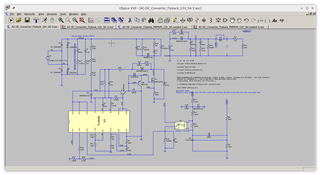
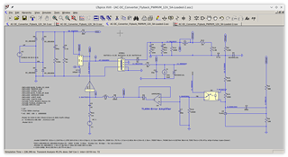
I have non-isolated Flyback and SEPIC designs using TL494 which are working. I have used the output transistors In both CC and CE connections without issues.

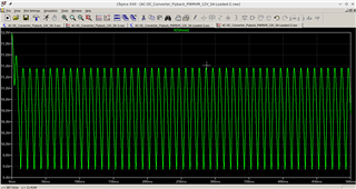
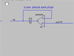
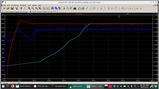
But now that I am using isolated designs, the circuit simulates well in low load, but cannot take any appreciable load. My guess is , connection from Opto-coupler to TL494 EA is the source of the problem.

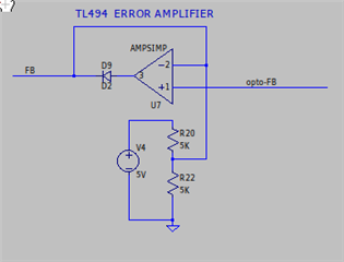
I am reading Isolating the Control Loop Bob Mammano ( TI document ). My question is, 'is the error amplifier in TL494 also an OTA ? Does Bob's comments on UC3524 - EA apply to TL494 too ?

Are there any specific recommendations to connect opto-coupler to EAs on TL494 / SG 3524 and other controllers of this family exist ?

Thanks in advance.

P Bhat

  • Hi,

    If you provide your circuit drawing, I can help to check if your opto connection is ok or not.

  • Hi,

    Can I give you my LTSpice simulation file ? Would you mind having a look at it ?

    The following is the transient simulation file. Not able to get it to work.

    However, PWM Average circuit is functioning in AC mode well. In transient mode, output voltage is oscillating.

    Can opto-coupler output be connected to FB pin of TL494 directly ?

  • Hi,

    What is CFB on IN1 how much voltage is CFB?

    What is your intention to connection R31 to GND?

    I can check you circuit where possible wrong like the above. But we are not supporting LTSpice

  • CFB is 0.1V, my peak current estimated at about 2.8A,sense resistor 25m.

    What you said about R31 is correct. That is not what I tested. I was in the midst of changes when screenshot was taken.

    I think I have got it by trial and error. Follows what worked.

    What did not work.

    This connection is what I see in TI implementation. This connection gives me 'timestep too small' in SPICE simulation, whereas the first variant converges well.

    My result.

    Connecting opto direct to FB also gives 'time-step too small error'. I guess opto does not like the 0.7mA sink on FB.

    Comments,if any,welcome.

  • Hi,

    On the not working one, you may check FB - I think in a close-loop feedback. opto would increase to a higher number until FB shows response. Your feedback control is actually from TL431. Your worked one is that you added another REF point to help move opto-FB.