This thread has been locked.

If you have a related question, please click the "Ask a related question" button in the top right corner. The newly created question will be automatically linked to this question.

TPS61165: External PWM dimming

Part Number: TPS61165

Hi All,


I have a question about "9.2.2 Additional Application Circuits".

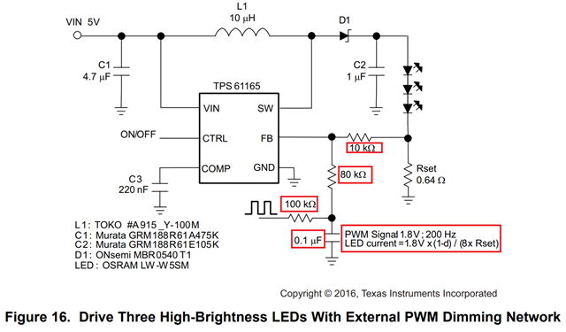
1. Is it possible to adjust the PWM Duty from 0 to 100% in the circuit of fig.16?
2. In the circuit of fig.16, 1.8V PWM signal is input. Is it okay to input 3.3V signal?
3. Please tell me the PWM frequency range of the circuit of fig.16.
4. Is d in the formula " LED current =1.8V x (1-d) / (8x Rset)" a PWM duty?
5. Are 100kΩ and 0.1uF of the circuit of fig.16 for PWM smoothing? Also, are 80kΩ and 10kΩ the ratio of Rset (8xRset in the formula)?
6. Please let me know if there is anything else you need to be aware of in the fig.16 circuit.


Best Regards,
Ishiwata

  • hello Ishiwata

    1. Yes, 0% duty cycle will lead to 351mA in this application, 100% duty cycle will lead to zero led current

    2. if 3.3V is used, the LED current formula will be different, LED current=(1.8V-3.3V*D)/(8*Rset)

    3. By using external PWM like this, no limitation on the PWM frequency range.

    4. yes

    5. yes, for filtering; yes

    6. You can refer to this application note

    How to Use Analog Dimming With the TPS6116x.pdf

  • Hello Wang,

    Thank you for your reply.I have additional questions.
    In the material of slva471.pdf (How to Use Analog Dimming With the TPS6116x.pdf), the circuit diagram below (left) is shown.
    I want to change the position of the C2 capacitor (right).
    Is there a problem with changing the position of the capacitor? If so, please tell me the reason.

    Best Regards,
    Ishiwata

  • hello Ishiwata

            Per my understanding, this series circuit of diode and resistor is a snubber to absorb voltage or current spikes. Therefore, for most of the time, the series circuit does not conduct, so the position will not impact normal operation.

  • Hello Wang,

    Thank you for your reply and wonderful support.I have additional questions.
    This is what I asked earlier about the external PWM circuit.
    What does 1.8V mean in the answers below?
     
     " 2. if 3.3V is used, the LED current formula will be different, LED current=(1.8V-3.3V*D)/(8*Rset) "

    It will be negative when calculated, is this correct?


    Best Regards,
    Ishiwata

  • hello Ishiwata

          Yes, you are right. If we just apply 3.3V and do not change the resistor values, this will lead to limited PWM duty cycle range.

          So if we try to use 3.3V as PWM high level, the resistors 10k,80k need to be modified to fulfill whole duty cycle range. 

          To make it convenient, customer can refer to the design tool, the link is in the PDF document 

    How-to-Use-Analog-Dimming-With-the-TPS6116x