This thread has been locked.

If you have a related question, please click the "Ask a related question" button in the top right corner. The newly created question will be automatically linked to this question.

LM5176: Asking for the LM5176 EMI design suggestion

Part Number: LM5176

Hi Sir,


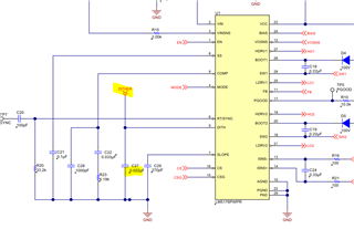
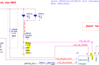
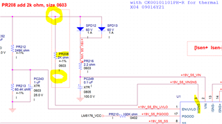
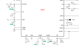
My customer would like design LM5176.

However, customer has some EMI issue. Customer provide the EMI test report here and customer also use LM5176. The EMI test result is similar.

CE_Mode1_DC IN 48V, Load.pdf

Would you please review report and provide your comment?


BR,

SHH

  • Hi SHH,

    Is it conducted emission measurement?  The 314kHz seems to be the switching frequency.  A quick fix should be enabling the LM5176's frequency dithering function.  If it still cannot pass, they may need to modify their input EMI filter.  Please try to enable the frequency dithering function first. 

    Thanks,

    Youhao Xi, Applications Engineering

  • Hi Youhao,

    The frequency dithering function has been enable on LM5176 demo board EMI 84.22 db too high.

    Do you have the EMI test data for customer?

    BR,

    SHH

  • Hi SHH,

    The customer's report does not look like enabling the dithering function.  Could you double check again?  What do you mean by 84.22 db while the maximum emission is 61 db in customer's report?

    Thanks,

    Youhao

  • Hi SHH,

    I may see where the confusion came from.  See below, the factory default setting of dithering is disabled by the switch S3.  You need to enable it by make S3 contact to be moved away from position 1.   Once the dithering is enabled, you can see its on the emission spectrum, which will have widened but tip-clipped top of the emission peaks.

    Thanks,

    Youhao

  • Hi Youhao,

    thanks for feedback.

    The pin 2 was short to ground duriing surge test 6kv is injected.  

    custoler would like to add 10u to PC249 location to test again. P

    If The pin 3 is short to ground as surge test 6kv is injected., culd customer improve surge test for pin 3 to add MLCC decoupling on top of PR208 or bottom of PR208?  

    Do you have concern for this modification?

    BR,

    SHH

  • Hi SHH,

    Regarding VIN pin, I would like to raise the 2.1Ohm resistor for better protection to 20ohms or higher, too.  Adding a TVS should help there. 

    Regarding VISNS pin, we do not recommend a large capacitor there, because a large delay of the sensing of the input voltage should be avoided.  Please consider to use a TVS.  

    You may consider to just use one TVS at the input voltage rail to protect both VIN and VISNS by a single protection device.

    Thanks,

    Youhao

  • Hi Youhao,

    thanks for feedback.

    does customer need to separate AGND and PGND?

    BR,

    SHH

  • Hi SHH,

    Yes as we always recommend.  This prevents the noise on PGND from affecting the control signals on AGND.

    Thanks,

    Youhao