

Datasheet P16 is described about inductor and ripple current.
Example case is described 25%, but equation is using "×0.4".
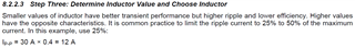
If there any reason or background for above difference, please let me know.
Best regards,
Satoshi
Datasheet P16 is described about inductor and ripple current.
Example case is described 25%, but equation is using "×0.4".
If there any reason or background for above difference, please let me know.
Best regards,
Satoshi
