This thread has been locked.

If you have a related question, please click the "Ask a related question" button in the top right corner. The newly created question will be automatically linked to this question.

TPS552882: maxim output current value

Part Number: TPS552882
Other Parts Discussed in Thread: , LM5176

Hi there,

we found TPS552882 maxim output current value is confusing.

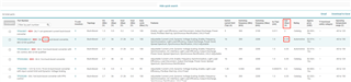
1. In the product selection list, the table shows the maxim output current value is 6.35A, as below image.

2. But the Average inductor current limit in datasheet is 16.5A typical.

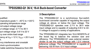
3. and in the description "The TPS552882-Q1 is capable of delivering 100 W from 12-V input voltage."

4. and there are many efficience test figures, from figure 6-1 to figure 6-10, the maxim output current is less than 8A.

5. the webench says the thermal issue would occur, when the output current exceed 6A.

we need this part output 15A, when the input voltage is from 9 to 16, and the output voltage is 12V.

Could this part meet our design goal? 

the other question is what's the real value of Vsns, the spec descript the same condition with different value, as below image.

  • Hi Yao,

    TPS552882 has two different output limit protections: 1. Inductor average current limit, it is 16.5A typically. 2. Output average current limit, which is set by ISP, ISN pin. The maximum output current limit is 50mV/Rsense.

    Please always follow the datasheet.

    For your application, TPS552882 cannot output such a big output power. Please consider using the buck-boost controller.

  • Hi Zack,

    Nice to get your reply, and thanks so much for your promot action.

    To be honest, I have read the datasheet again, but I still can't understand the reason of "TPS552882 cannot output such a big output power".

    Looks like the datasheet shows the output current could reach 16.5A, but why this part cannot output 12V and 15A.

    What's the limitation of this part for higher current with 12V output application?

    And the maximum output current limit is 50mV, but the datasheet has 30mV spec at same test condition, which makes me confused.

  • Hi Yao,

    There are two limitations:

    1. TPS552882 inductor average current limit could be configured to maximum 16A typ, 14A min. The current limit tolerance should be took into consideration.

    2. If outputting 12V, 15A, 180W, the IC temperature rise would be extremely high and cause thermal shutdown.

    Please ignore the 30mV spec row. We will fix that typo. Thanks.

  • Hi Zack,

    Thanks for your kind reply, really appreciate your help and information, our team and I got much more confident under your guidance.

    I can understand limitation 1, but for the limitation 2, I still have some question.

    How could we evaluate the IC temeprature rise based on different output current? or in other words, how could we confirm the boundary of the output current and voltage?

    In my opinion, the power consumption of TPS552882, consist of two part, one is the MOSFET Rdson heating, and the other one is switching power.

    The Rdson of TPS552882 is about 7mohm, and the max average current is about 14A, and then the Rds power consumption is about 1.37W.

    And the thermal Rjb = 12.8℃/W, so the temperature rise is about 17.5℃, is acceptable.

    The other part is power switching consumption, how to calculate this part's influence?

  • Hi Yao,

    You can use TPS552882-Q1 calculation tool (on ti.com TPS552882 web page) to get the calculated rough IC temp rise.

    Assume you use the device in buck mode and Vin is 16V, the conduction loss is ~14A*14A*7mohm=1.37W. The switching loss also needs to be took into consideration, it could be calculated roughly by: (tr+tf)*fsw*Vds*I=20ns*400k*16V*14A=1.8W. If only considering these two, the total is 3.2W.

    The device Junction-to-ambient thermal resistance is 47.5C/W so IC temp rise is 152C.

  • Hi Zack,

    Could we use a good cooling for TPS552882, such as adding heat sink on the IC top side to achieve the design goal?

    the Junction-to-case (top) thermal resistance 23.8C/W, 3.2W will lead to 40.96C timp rise.

    Thanks again.

  • Hi Yao,

    No. We still don't suggest. 

    The reason is for your application: Vin 9-16V, Vout: 12V, 15A. In Boost mode, it will trigger the device average current limit. For example, when Vin is 9V, input average current = inductor average current = 12V *15A/0.9/9V = 22A>15A. 

    You could take a look at buck-boost controller LM5176. The four MOSFET are external.

  • Yes, thanks for your reminder, as your mentioned, there is an issue for the low input voltage under boost mode.

    So the maxim output current depends on the thermal performance and the maximum Internal Mosfet Average current value, which is about 14A.

    Is it right?

  • Hi Yao,

    Yes, you have to consider the IC thermal rise and switch current limit in worst case when selecting a dc/dc converter. TI Webench could help recommend some devices for you.