This thread has been locked.

If you have a related question, please click the "Ask a related question" button in the top right corner. The newly created question will be automatically linked to this question.

TLC5971: SDTO&SCKO issue

Part Number: TLC5971

Hi

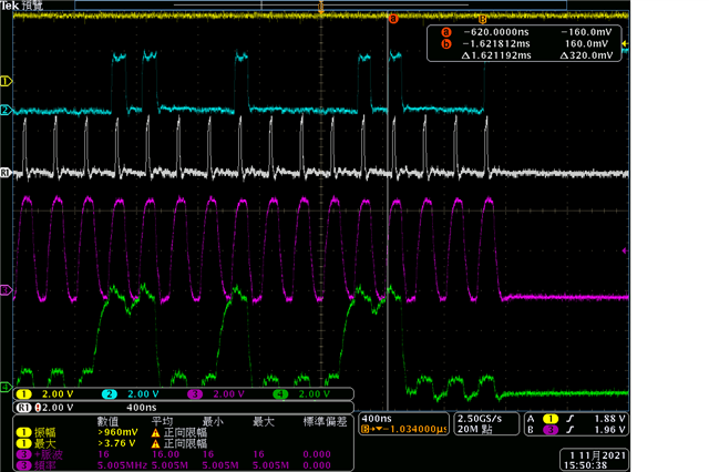
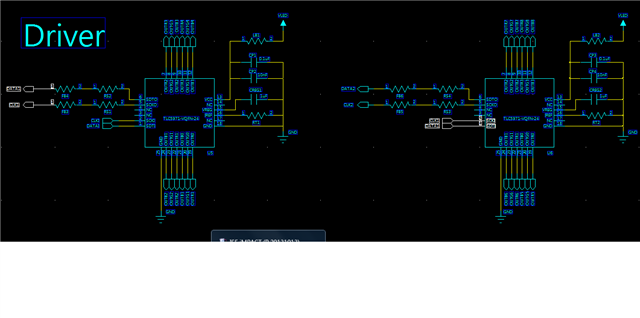
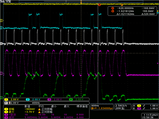
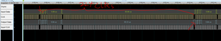
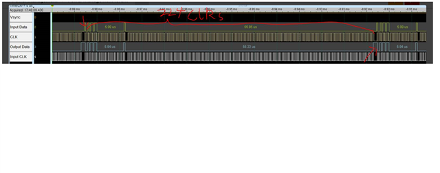
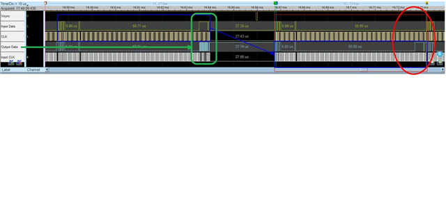
When the customer lights up the TLC5971 light bar, they find that if the OUTR0 of the first driver is turned on, some strange data will appear in the SDTO and SCKO output waveforms of the driver, causing the OUTR0 of the second Driver to be lit (see attachment) , thanks.


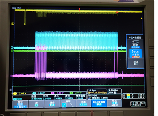
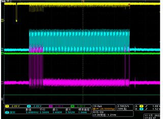
Red wave: SDTI of the first driver
Green wave type: SCKI of the first driver
Blue wave type: SDTO of the first driver, SDTI of the second driver
White wave type: SCKO of the first driver, SCKI of the second driver

  • Hi Gareth,

    Could you help to point which data is abnormal, the same data with SDTI/SCKI of first driver? And what is the expected behavior of the second driver in customer's code ? 

  • Hi Hard

    Corrected as follows

    Red wave: SCKI of the first driver
    Green wave type: SDTI of the first driver
    Blue wave type: SDTO of the first driver, SDTI of the second driver
    White wave type: SCKO of the first driver, SCKI of the second driver

  • Hi Gareth,

    Yes I knew the red waveform is clock signal. The full data package is 224*2 bits and I cannot see the meaning form this part. Could you help to point what in the waveform customer think is abnormal? Also I think a logic analyzer could help to show the test results clearly.

    Another question is for customer's code, how the second device is programed?

  • Hi Hardy

    1.) The customer would like to ask why abnormal blue and white waveform appeared after the first TLC5971, which caused the second lamp to be driven. 

    2.)At present, the serial signal to light up the Driver only has the data required to light up the OUTR0 of the first Driver, and the commands (6-Bit Write Command and 32bit of b217~192) required by each Driver are as follows:

    "100101" & '1' & '0' & '0' & '1' & '0' & BCB(6:0) & BCG(6:0) & BCR(6:0);

    Write CMD => "100101"

    OUTTMG => '1'

    EXTGCK => '0'

    TMGRST => '0'

    DSPRPT => '1'

    BLANK => '0'

  • Hi Gareth,

    Shift-register is inside the IC between signal input and output pins. If customer keep sending the same data, it is possible that the out put comes out the same data as input.

    Could you help to confirm that  1) Is customer send the control signal once or continually sending? 2)whether this waveform captured at the first data sent to IC?

  • Hi Hardy,

    1. The SDT & SCK signal is follow below picture.

    1. The SDTI and SCKI input of the Driver are continuous signals, and the signal only lights up the OUTR0 of the 1st Driver.
    2. We measure the SDTO and SCKO of the 1st Driver (also the SDTI and SCKI of the second Driver) and find that the signal is regenerated from 1st driver and sent to the 2nd driver that cause the OUTR0 of the 2nd Driver to be lit.
    3. No LED is lit after the 3rd driver.
    4. We think the regenerated SDT and SCK signal from 1st driver to cause the 2rd driver to be lit, but we only send the signal at the end of serial data, the signal should be keep in 1st driver shift register and that can not to serial out from 1st driver.

    thanks for your help.

  • Hi James,

    Is there a waveform captured by logic analyzer to see the whole signal clearly?

    The waveform showed above is captured in the red rectangle timing?

    Let's say the whole 224 bits as one data package. Could you help to test if you only sending one data package but do not keep writing the same data? If it is confirmed that SDTO and SCKO generate the signal immediately when SDTI and SCKI have data input, this is an abnormal behavior, could you help to do an A-B-A test to see if the IC is abnormal one?

  • Hi Hardy,

    Reply as below.

    1.Is there a waveform captured by logic analyzer to see the whole signal clearly?

    Reply: The attachment is waveform capture, please refer to it. You can download the software at the following URL to open the file

    TLC5971.zip

    www.acute.com.tw/.../MSO_InstallPack_1479.zip


    2.The waveform showed above is captured in the red rectangle timing?

    Reply: Yes, we sent 256 driver serial data in one frame (1/60Hz). The total number of SCK times is 57344, so the frequency of SCKI is 3.5MHz. Except for Write Command, Function Control, BC and 1st driver OUTR0 have data in SDTI , Other GS are zero. You can refer the attachment.

    3.Let's say the whole 224 bits as one data package. Could you help to test if you only sending one data package but do not keep writing the same data? If it is confirmed that SDTO and SCKO generate the signal immediately when SDTI and SCKI have data input, this is an abnormal behavior, could you help to do an A-B-A test to see if the IC is abnormal one?

    Reply: We will arrange time for testing, but you can refer to the following waveforms, you can find that SDTO&SCKO (blue and white waves) are regenerated according to the rising edge of SDTI&SCKI(green and red waves) and the data is also the same.

  • Hi Hardy

    Any comments?

  • Hi Hardy

    The customer's case is a multi-string application, is TLC5971 suitable for use? Or have other comments or ideas? 

    Thanks

  • Hi Gareth,

    It is 224-bit shift register inside TLC5971 and the output data would come out after 224 clocks, comparing with input data. From the data you captured, you can say the output data is the same as input data, but also can say the output data is behind input data exactly 224 clocks. It is hard to determine whether the device works abnormally.

    What I suggest to test is 1) only send one 224 bits data packet, to see if output have data comes out. 2) add some idle clocks between 2 data packets, to shift the phase the input data and output data.

  • Hi Hardy

    Thank you for your support

    The previously provided LA output (MSO_InstallPack_1479.zip) can be opened (see the figure below), which already contains the data of the entire Frame, just move the waveform to the rightmost (the last point of Data input) to see the first Driver Output Data.

  • Hi Gareth,

    I do not think customer's conclusion is right, that the output data is following input signal. As you can see below plot, the sync signal starts a input data series. In the red round SDTO is not the same as SDTI, as you can see several LSB of output signal are 1 while input signal are 0. The first 224 bits output data packet in blue rectangle is the same as the last 224 bits input data packet, which is stored in shift register in the last writing cycle.

  • Hi Hardy

    We think when the controller transmits serial data to the input of the first TLC5971, the serial data immediately appears at its output. Please refer to the picture below (green frame). This is the fundamental reason why the second TLC5971 is also lit when the first TLC5971 is lit.

  • Hi Gareth,

    Firstly, I think we need to clarify if the output data is come out from input data immediately. From the waveforms I think it is not. The evidence is the waveform in red round. Output data is not the same as input data at the same time.
    My theory is that customer was continually sending the same 224 bits data packet again and again. Since output data is delayed with input data with 224 clocks. It looks like the output data appears immediately with input data, but actually is .
    To clarify it clearly, I think customer could do the tests
    i: 1
    ) Powering up the device. 2) Only send one data packet. (do not keep sending other data) 3) Capture the waveform of SCKI/STDI/SCKO/STDO.
    ii: add some blank data between 2 data packets, like 0 in 20 clocks, to make the phase shifted some clocks.
    iii: send different data between 2 data packets, like shifting with all 0 and all 1.

    For why the second TLC5971 is also lit when the first TLC5971 is lit, I think it is because the latch pulse is not generated after the first data packet and the data is shifted to the second driver. If customer want to only illuminate the first driver, the internal latch signal need to be triggered after each 224 bits data packet. The SCKI need to be blank at least 8 clocks.

  • Hi Hardy

    According to your suggestion, the customer will only send the data of one Driver (60 times per second), the waveform and phenomenon as attachments.

  • Hi Gareth,

    Is it OK to ship 2 boards to me? I will send you my address through mail. Thanks.