This thread has been locked.

If you have a related question, please click the "Ask a related question" button in the top right corner. The newly created question will be automatically linked to this question.

LM5022: LM5022 Oscillates

Part Number: LM5022


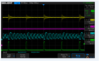
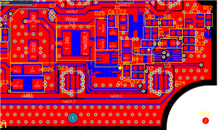
I am using a LM5022 and can not get to run stable.  I never see the sense pin get to .5 volts and it oscillates terribly.  Can i get some support on what i am doing wrong.  I used TI web tools to do the design which basically 24V in 53V out at 1 Amp.

thanks

  • Hi Scott,

    can you share some more details:

    - does it only oscillate during full load

    - what is the output voltage - does it reach it level and oscillates around that or is already the ramp up oscillating

    - can you share the schematic or Webench design.

    - which softstart time have you set and can you see the ramp on the softstart pin

    Best regards,

     Stefan

  • Stefen,

    I would be glad to share my design but i am new to TI form.  I used web design to calculated my values using LM5022.  I would be glad to share but need to know how i can share it.  Basically output voltage 53V @ 1 Amp.  I have three hysteretic converters feed by this supply.  I am defiantly seeing oscillations at start up as it ramps up.  The oscillations cause large input currents which i ca not have.  I need it to be stable at all times.  I have 10nF on my soft start currently.

  • I failed to note my input voltage is 18-24 DC

  • Hi Scott,

    the 10nF should give a startup time of around 500us.

    Can you measure the voltage on the softstart (SS) pin. It should give a ramp and then a stable fixed voltage.

    Otherwise and overcurrent might be detected and the converter tries to restart. In this case you need to increase the Softstart Cap or decrease the load.

    Best regards,

     Stefan

  • Stefan,

    I am basically seeing the supply really not being stable at all loaded including start up.  When I load the supply down with my 3 other LED drivers which are hysteretic converters i am basically see the supply oscillate thin shut down as i drive them at 60 Hz.  Is it possible my layout is causing this instability?

  • Hi Scott,

    yes, the layout can cause this issue as well. Most properly due to the Current Sense resistor seeing noise and cross talk.

    For the next step let us test if the is an overcurrent detected. For this please measure the waveform on the SS pin.

    Best regards,

     Stefan

  • Stefan,

    I measured the SS pin and it ramps up as you indicated and stays at a stable voltage.  Yet the supply still keeps shutting on an off as i drive my 3 LED drivers.  They turn on oscillate a bit then turn off.

  • I did try increasing the SS cap value but it had no effect.

  • Hi Scott,

    OK, good news is that is not getting an overcurrent condition. So at least one point we can exclude.

    So let me summarize to ensure I got all right:

    - You see the stability issues even without load

    - You load is dynamic an switches with 60Hz


    Can you make a few measurements with a scope (good would be to have them in one screen:

    Vin
    Vout
    switch node (Between L1 and D1)
    Out pin of the LM5022

    How is your layout? Have you running GND return paths through the sensitive area with RT and Current sense?

    Best regards,

     Stefan

  • i sent you an email of the measurements you requested.  Just in case you did not receive them i will do it again here.

    This is scope shot of unit running with no load.

    Yellow: Vin

    Purple: Vout

    Blue: L1 & D1 node

    Green: Out Pin

    This is scope shot of unit loaded with my 3 hysteretic LED drivers, driven at 2.5A  500uSec on time at 60 Hz.

    Thanks

    ScottC

  • Hi Scott,

    Are interpretation right:

    - it looks stable without load - first picture

    - The Output gets instable when the load is on (every 16.6ms for ~ 4.4ms)

    At which time in the scope plot the load is activated? When the VOUT dips? Why is the reaction for higher burst on OUT then so slow?
    From the Webench data the crossover frequency is very low (@1kHz) - it might be good to optimize this to get this higher

    You might can try the values in the attached screen shot - it is done with the power stage designer tool (can be found on the TI web page)

    Can you Zoom in into the burst blocks?

    Thanks,

     Stefan

  • Stefan,

    Honestly to me it seems it is not quite stable even unloaded. There is still a gitter in the gate drive unloaded.  I will try changing the values using the application.

    Attached is the a zoomed in scope shot of the one of the burst blocks.

    here is my layout of the power supply

  • Hi Scott,

    thanks for highlighting this in the loaded plot, does not recognize this on the first look.

    Please let me know the results with the updated values.

    I will review the layout later today or tomorrow.

    Best regards,

     Stefan

  • Hi Scott,

    from the layout it looks like that there is a short between LM5022 VCC and OUT pin at the R4. Can you please check this?

    It also looks like that the Ground plane of the right side of the LM5022 has a quite long path around on the bottom layer to get to the active part.

    This could make a large loop for the Current sense input and make this more sensitive to noise.

    Best regards,

     Stefan

  • Hi Stefan,

    thanks for helping me.  There is no short and yes the lay out of the ground is not optimal for this board.  I will fix it for the next prototype.  I was able to change the compensation values as you suggested and it did help in eliminating the on and off oscillations.  I was also able to get it to run with all  my LED drivers running.  I have spun a new board with corrected layout and will test it when it arrives.  thanks again for you help!  I do have a question though i notice when its running and monitoring the gate drive it still does not actual settle on a frequency it seems to gitter a bit, is this normal, or should it be stable all the time?

    Thanks

    Scott

  • HI Scott,

    When you have a boost design with a duty cycle above 50% you need to use slop compensation, this is controlled by the cap on the SS pin with the used controller. More info and the theory can be found here:

    Understanding and Applying Current-Mode Control Theory (ti.com)

    But basically the large jitter between short and long pulses is reduced but there is still a slight jitter.

    To ensure we have the same picture in mind. The frequency is fix but the duty cycles varies a bit.

    If the frequency varies then the is a disturbance injected into the RT pin and/or the Rt resistor.

    Best regards,

     Stefan

  • Hi Scott,

    It's been a few days since I have heard from you so I’m assuming your question has been answered.
    If this isn’t the case, please click the "This did NOT resolve my issue" button and reply to this thread with more information.
    If this thread locks, please click the "Ask a related question" button and in the new thread describe the current status of your issue and any additional details you may have to assist us in helping to solve your issues.

    Best regards,
    Stefan