This thread has been locked.

If you have a related question, please click the "Ask a related question" button in the top right corner. The newly created question will be automatically linked to this question.

LM1084: Unable to define resistance load in PSPICE for TI

Part Number: LM1084
Other Parts Discussed in Thread: TPS7A47

Hi, 

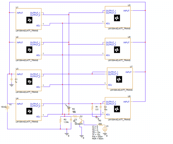
We are trying to design a voltage regulator, and we need an output of 2A from each one of the LM1084 regulators that are present in our circuit (I wasn't able to upload the .opj file so I'm attaching a screenshot).

I'm unable to define a 0.5 OHM load at the output. After running the simulation, I receive the following error:" Less than 2 connections at node GND".

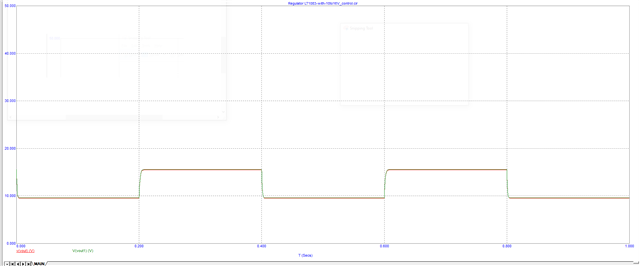
 we need to verify the output current (2A from each output rail) with the simulation, can you please assist?

Thanks! 

Anna

  • Hi Anna,

    This error is normally caused by a net that has only a single connection, but I don't see an obvious reason why you are getting this error.

    Besides the PSPICE error, what you are trying to do here will not work in a real application as-is. You cannot directly connect the output of LDOs together as you have done because of the inherent differences between the devices, but you can connect them together if you use a ballast resistor at the output of each. Here's a reference design that goes over the design of such a circuit:

    https://www.ti.com/lit/ug/tiducs7/tiducs7.pdf

    Regards,

    Nick

  • Thank you Nick, Is it possible to send you the simulation file ? It seems that the problematic node is the connection to ground of R1 and C2, because when I cut out the load part, it works. I can't figure out how to connect the load without getting an error.

    In addition, we do want to put a resistor on the output of each LDO. Can you advise about the minimum resistance that is required? 

    Thank you for your assistance, 

    Anna

  • Hi Anna,

    Now that I think about it, I believe LM1084 is not a good device for this paralleling idea for a couple reasons. The main reason is that the document we have that describes how to parallel LDOs assumes the use of a device that has an NR/SS pin so that the internal references can be connected, which eliminates errors associated with inherent reference voltage differences between devices. This brings another issue with it, which is that we do not have equations for calculating the size of the ballast resistors when this extra error source is present. 

    I've looked around and the part that best fits what you are trying to do is TPS7A47, but it is only a 1A part, so you would need to parallel twice as many of them. Unfortunately getting large currents with a high input and output voltage is a difficult thing to do so our portfolio is relatively limited for devices like this. 

    Regards,

    Nick

  • We don't have a space problem because this board is dedicated for testing. If we use the TPS7A47, we need to connect 16 of them in parallel. Do you think the error can be eliminated for so many devices in parallel? 

    Basically,  we need to design a regulator that outputs voltage between 10V and 16V, with output current of 20A. 

    The transient response needs to be something like this (this is an output from a similar microcap simulation):

    Thanks! 

    Anna

  • Hi Anna,

    I haven't seen this many devices paralleled before, but TPS7A47 is among the best devices to accomplish this because of the NR pin and the high accuracy matching that the ANY-OUT architecture provides. 

    A question, though: Do you need it to be dynamically adjustable between 10V and 16V or just need the output to be within that range? If it is the latter, this paralleling architecture is well-suited because there will inherently be some loss across the ballast resistors. 

    Note also that the ballast resistor for each device can be made smaller by using each device farther from its current limit, so if you have the board space it might be better to use a few extra devices so that each one provides less current. You can see this in Equation 2 from the app note I linked above. Again this might not be so much of an issue if your output voltage just needs to fall in the range 10V to 16V.

    Regards,

    Nick

  • Unfortunately, we need the output to be an AC signal between 10V and 16V, if I understood your question correctly. Those limits are constant but we do need a changing output with adjustable frequency range between 15 Hz to 1Khz. 

    Do you believe that a two stage solution with an opamp for feedback implementation and a transistor for current amplification is an easier one? With a proper heat sink ,of course. If so, do you have a suggestion for a suitable op-amp ?

    Thanks, 

    Anna

  • Hi Anna,

    I'm a little confused now. You are saying you need a sinusoidal output from the LDO? 

    Can you more fully describe what you are trying to accomplish? Here's a summary of what I think your requirements are: 

    VIN = 18V

    10V <= VOUT <= 16V @ 1kHz - 15kHz (sinusoidal? PWM?)

    IOUT = 16A

    Regards,

    Nick

  • You are right, I'm sorry I wasn't clear. Our requirements are: 

    - An AC signal, isn't necessarily a sinusoidal. 

    - 10V <=Vout<=16V @ 15HZ - 15KHZ (or as close to this full frequency range as possible).

    -Our new current demand is 30A max. 

    We know that there are supplies in the market that can provide us with this signal but they are very expensive. We want to explore the option to design a board that will be connected to a more basic waveform generator (BNC Model 645) or/and a DC power supplier and provide us the 30A current we need. 

    The LDO parallel configuration probably won't work because it seems like too many devices in parallel. Maybe you have a class D amplifier that can work for us? 

    Thanks, 

    Anna

  • Hi Anna,

    In that case I would suggest moving towards an amplifier as you mentioned because this is not how LDOs are intended to be used. However, I'm not sure that you will be able to get 30A from that kind of solution. You will need to post a new question on the forums for one of the amplifier groups.

    Regards,

    Nick

  • Thank you for your support Nick, this thread can be closed now.

    Anna