This thread has been locked.

If you have a related question, please click the "Ask a related question" button in the top right corner. The newly created question will be automatically linked to this question.

UCC21520: Driver blocking pulses

Part Number: UCC21520


Hi

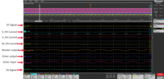
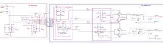
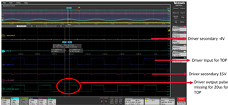
I was using UCC21520 in one of our application(Inverter). DC bus voltage is 48Vdc. Secondary of High Side drivers are supplied by each  isolated flyback converter and all three low side drivers are powered with single flyback converter. output of flyback converter is +15V and -8V. With inductive load suddenly the driver output is not same as input. as show in below image for top. Driver output for top going low for some duration even when primary of input is high.  

I have change the Rgon from 10ohm to 5.6ohm and Rgoff from 5.6ohm to 2.2ohm. still the problem remains same. During testing i also monitored the supply voltage levels at totem pole transistor(booster) Q5 and Q6 collector as below image . They are stable and no issue found. Also checked DT pin and Disable pin status they are also healthy.

I would like to know what could be the reason for driver blocking the pulse.

Regards

Bharath Gilla

  • Hello Bharath,

    Generally, the causes of missing pulses comes down to poor filtering on the DT pin or noise on the output pin. From your description I believe that the DT pin filtering isn't the issue in this case and I would like to investigate the output side of the driver. Could you take these same scope shots with unfiltered scope channels? That way we can know if that bandwidth filter is masking noise on the output pin. OUTA waveforms should be taken as close to the pin as possible. I am curious about your layout as well; could you provide some pictures? If noise is in fact the issue we might recommend a ferrite bead, but lets take a look at the unfiltered waveforms first.

  • Hi Krystain

    Thanks for the response. Please find the below image. We are not seeing any difference by changing the bandwidth limits. In our application driver and booster (totempole circuit) is placed in one board and 8 MOSFETs are parallel for each switch in another board(metal clad pcb). pwm signal to MOSFET is given via board to board connector. Also please find the below points.

    1. This problem is observed only in High side U-phase driver. No problem in Low side of driver or other phases. I have change the driver board or power board issue is same.

    2. With no MLCC capacitor connected across the DC bus near the MOSFETs issue starts around phase current 30Arms. I tried to place 3uF(three 1uF/100V parallel at each leg) issue starts around 150Arms.

    Can i have offline discuss to share the layout and other details.

    Regards

    Bharath Gilla

  • Hi Bharath, I received your request, I'll follow up with you on this through private messages.