This thread has been locked.

If you have a related question, please click the "Ask a related question" button in the top right corner. The newly created question will be automatically linked to this question.

LM5116: LM5116 design review

Part Number: LM5116

Hi Team,

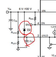
Could you help to check the possible root cause of the problem of this design circuit from our customer. I have attached the PDF file that contains the buck regulator schematic.

They designed a circuit using Webench, and copied it into Orcad. Then created a PCB test piece. When they power the board and slowly increase the supply voltage the Vcc comes live. If they continue to increase the supply the UVLO rises to 1,2xx volts. As soon as the supply voltage exceeds the threshold, the voltage on UVLO falls to zero. Vcc also falls to zero

It is necessary to reduce the supply to zero before the voltage on UVLO can be re-established.  

One thing that has just notice by the customer but  I am not sure if this is the cause of the problem.
The copper pad under the chip although there it is covered with resist, so that the pad does not connect to the plate. Could you tell us what would happen if the EP is not connected to GND?

Buck Regulator.pdf

Thank you in advance!

Best regards,

Jonathan

  • Hello Jonathan

    If the EP is not connected to a large ground plane, there is a possibility that the device temperature increases and triggers Thermal Shutdown. 

    In your case, I think a hiccup mode protection is triggered. Please read the section 7.3.3. of the datasheet and also consider to add a capacitor and diode at the UVLO pin. 

    - Eric Lee (Applications Engineering) 

  • Hi Eric,

    Here is our customer's feedback as shown below. 

    When the UVLO pin is taken above 1,215V the pin is instantly pulled down to a few 10's of mV, not the 200mV mentioned in the paragraph 7.3.3. Vcc  also falls to zero. The UVLO pin stays low untill the supply is taken to zero.
    I have shorted the current monitor resistor, thereby preventing a current surge being "seen".
    At the instant of the UVLO pin being internally pulled low there is no activity on the MOSFET drive pins. I can't see that there is an over-temp event
    Best regards,
    Jonathan
  • Hello Jonathan 

    Did your customer added D2 diode and CFT capacitor as it is suggested in the figure ? 

    Would you please do one experimental test for me ? Please remove the inductor and check if the UVLO pin is pulled down or not during start-up. 

    - Eric Lee ( Applications Engineering) 

  • Hi Eric,
    Here is our customer's response as stated below. 
    I fitted the diode and capacitor, without success. I had three boards made. One was incomplete because of component un-availability. One had the LM5116 removed, the solder resist on the EP padscrapped off and the chip replaced. Sadly the chip did not survive.
    The other board had the inductor lifted and the board tested. Still it did not function, (nothing happened)
    I have obtained an 12V evaluation board, and that works fine.
    As there have been no comments about the circuit design, I must assume that it should be good, and that the problem lay with the layout
    Best regards,
    Jonathan
  • Hello Jonathan 

    Please check these items when the board works.  

    • Make it sure that '0V' node is connected to 'GND' node
    • Increase sot-start-time by increasing C11. Please try 470nF. 
    • CS-CSG traces should be kelvin-connected to R26

    -Eric Lee (Applications Engineering)

  • Hi Eric,
    Here is our cusotmer's feedback below. 
    I had the lm5116 replaced on two boards, (on both boards I had the resist removed from the under chip pad). These were chips from RS, whereas the first chips came from Digikey.
    These chips behaved differently. UVLO voltage did not get internally pulled down when the voltage exceeded the 1,215 volt threshold.
    Additionally the VCC voltage remained, (at approx. 7V).
    The C11 has been increased to 1uF. R26 is Kelvin connected, and 0V and GND are connected
    The circuit still fails to work
    Best regards,
    Jonathan
  • Hello Jonathan 

    Can you capture some waveforms for more investigation? 

    Please capture 1) VIN, UVLO, SS, COMP waveforms together without inductor. 2) VIN, SW, COMP, RT waveforms together without inductor 

    -Eric Lee (Applications Engineer) 

  • Hello
    I am closing this thread since I have not heard from you for sometime. If you are still trying to resolve the issue, please feel free to open a new thread or reopen this thread.  
    Thanks
    - Eric Lee (Applications Engineering)