This thread has been locked.

If you have a related question, please click the "Ask a related question" button in the top right corner. The newly created question will be automatically linked to this question.

LM2642: Efficiency, ULVO algorythm, broken down after working in ULVO mode

Part Number: LM2642

Dear sirs,

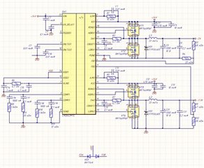
We have some strange situation with this device - LM2642. We've done our own design based upon the one presented in datasheet with some modifications based on nominal values calculation of inductors, capasitors and loop compensation circuits. Our design is the following:


What we are doing:

At the input of board we connected a power source with stabilized output and ablility to set the ouput power. At the output 3.3 V side of board (2nd output) we have a load consists of serial and parallel connected resistors of 2.1 Ohm with appropriate nominal power (about 1,57 A). 5V output (1st output) is broken (see case 2 below) and doesn't consume any power.

Case 1:

What we want to see:

When we powering our scheme with power source of (1.57 * 3.3) = 5.18 W the input current is about 0.23 A (0.215 A for the load plus dozen of mA for efficiency).

What we actually see:

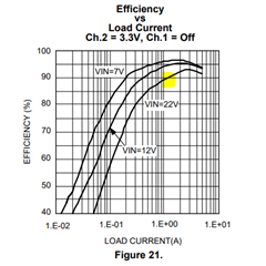
We measuring real current on 3.3 V load 1.33 A thus resulting the power of (1.33 * 3.3) = 4.39 W. Given input voltage equals 24.1 V (real measure) the input current is 0.21 A thus the power consumed from power source is actually 5.06 W. It equals that efficiency is about 87 %. I expected an efficiency of about 93-94 %. Were my expectations too optimistic?

Case 2:

Input power source is small enough to support such load current.

What we want to see:

Device should go into ULVO (Input Under-Voltage LockOut) and try to switch off external transistors to let the input voltage rise enough to return to normal mode.

What we actually see:

voltage at output diode:

in other scale:

and voltages input (blue) and VLIN (yellow):

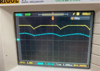
Input voltage goes below 5 V and current limited to about 0,7 A.

We testing the 3.3 V output for now because the first ouput of the device (5 V) is broken. We have three devices LM2642 with broken first output for now under the same situations: as power input goes low (or load goes high enough), ULVO mode is on for some time (about 30s - 2m) and then 0V forever at this output not depending how much power we have at the input.

Questions for case 2 are: 1) Does input voltage (below 5 V) in ULVO mode appears to be normal? 2) Why does the first output fail after some time of ULVO mode?

Thank you!

  • Hi Anton,

    Our US team will check it and reply you soon.

  • I'm not able to open the links because it gets blocked by web security. Would you please reshare it as an attachment or an image? 

  • Updated my question. Thank you for respond!

  • Case 1: Yes, the efficiency of 87% is expected at 24Vin. As you can see from Figure 21, it is close to what we also measured at 22Vin (as shown below). You will see an efficiency drop at a higher input voltage due to higher switching losses, etc.

    Case 2: Does the 5V output work at higher Vin (e.g., at 24Vin) or if you increase the input supply current? It is difficult to read the schematic because of the resolution. Still, assuming you have done the calculation correctly according to the datasheet, your PCB layout and the bill of materials are the next things to look at. 

  • Unfortunately 5V output didn't work in our experiment because it was broken earlier. 3.3V output starts working when we increase input supply current (given input voltage set to 24 V but because of small current set in power source it's about 5 V). At some level of input current LM2642 exits from ULVO mode and the input voltage become normal 24 V.

    I've included BOM as well as schematics & pcb layout.

    Thank you!

    Designator	PartNumber
    
    "C1, C7, C10, C11"	"0,01 uF,50V, 0603"
    "C2"	"1 uF,50 V,10%, 1206"
    "C3, C12"	"EEVFK1V471Q"
    "C4, C13"	"10 uF,35 V,10%, 1206"
    "C5, C8, C17, C19, C20"	"0,1 uF,25 V,X7R,0603"
    "C6, C22"	"2,2 uF,50 V,X7R, 0805"
    "C9, C21"	"EEEFPA122UAP"
    "C14"	"1 uF,10 V,10%, 0603"
    "C15"	"4,7 uF,10 V,X5R,0603"
    "C16, C18"	"1000 pF,25 V,10%, 0603"
    "DA1"	"LM2642MTC"
    "L1, L2"	"CDRH127/LDNP-220MC"
    "R1, R5"	"10 k,50 V,1 %, 0603"
    "R2, R6, R7"	" 4,7 Ohm,100 V,5%, 0805"
    "R3"	" 68 k,50 V,1%, 0603"
    "R4"	" 22 k,35 V,1%, 0603"
    "R8, R10"	" 1,1 k,50 ,5%, 0603"
    "R9"	" 47 k,50 V,1%, 0603"
    "R11"	" 20 k,35 V,5%, 0603"
    "R12"	" 28 k,42 V,1%, 0603"
    "R13"	" 12 k,27 V,5 %, 0603"
    "VD1, VD2"	"STPS3L60S"
    "VD3"	"BAT54A"
    "VT1, VT2, VT3, VT4"	"IRF7469PbF"
    
    av-tuk-14-pwr.PDF

  • Thank you for the information. 1200uF for the output capacitor seems excessive. If the output capacitor is too large, it will take longer for the output voltage to reach regulation. The under-voltage protection gets initiated if the output voltage is still below the regulation limit before the soft-start timeout.  Please remove the 1200uF and see if the problem goes away. 

  • When we removed this 1200 uF capasitor and leave only 2.2 uF at the 5V output (1st one) the IC went to the overvoltage protection mode as we supppose and switched off both output channels by opening bottom FETs. When we returned back this capasitor the LM2642 works correctly. We continue studying an IC behaviour in our scheme.

  • If reducing the output capacitor is not viable, another suggestion is to increase the soft start cap. This will help limit the inrush current and also gives more time for the VOUT to reach regulation before the soft start timeout, therefore preventing any false triggering of the current limit or UV protection.