This thread has been locked.

If you have a related question, please click the "Ask a related question" button in the top right corner. The newly created question will be automatically linked to this question.

TPS55165-Q1: Stability issues

Part Number: TPS55165-Q1

I am having stability issues with TPS55165-Q1.

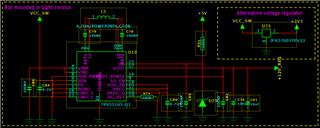
Here is the schematic:

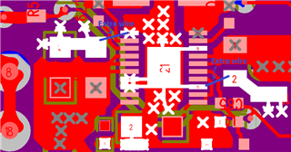
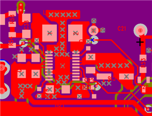
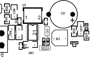
And this is how the layout look like:

The problem is seen when input voltage is around 11V and higher.

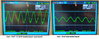
When input is around 11V the output is varying between 10.4V and 11.3V with a frequency of 300Hz.

Output @11V input

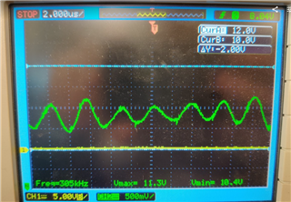
If starting with an input voltage < 11V and rising, the same "instability" is seen also on higher input voltage. But if starting with input voltage > 11V the output is stable also at higher input voltages.  

When searching around in this forum I found out that the layout is very critical. I have already done some layout changes but I'm not sure if these changes will solve my problems (The layout changes have not been tested yet).

The changes are:

* Removed the 100uF electrolyte cap and added 10uF ceramic instead

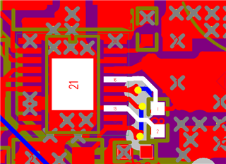
* Added a 100 nF ceramic cap between  pin 16 and 13. See picture below.

Is there anyting else that I can do to improve the layout? I have tried to follow the layout guidlines as good as possible. It seems that the problem is on the boost side.  

  • Hi Martin,

    Thank you for reaching out on E2E. 

    The datasheet table 7.5 Electrical Characteristics - External Components suggests the Cout in the range of 18uF ~ 47uF. Please try removing the 100uF electrolytic cap first because it may affect the loop stability.

    For the layout: The most critical part for this device is the input cap CINL and output cap Cvosn. Put the Cinl close to pin 4&5 so that Buck leg switching loop length is minimum. Put the Cvosn close to pin 16&17 and pin 13. 

    For the power trace: VINP, VINL, VOUT, VOUT_SENSE, L1, L2, GND, use wide copper trace. 

  • Hi Zack

    Thank you for your quick answer. I have tried to remove the 100uF capasitor but that did not help. I have also tried to solder 100nF capacitors between Vout and ground and placed it as close to the TPS55165 as possible but it did not help. Then I added short wires between the ground pins on TPS55165 and capacitors (see picture below), without any success. I have a 4 layer pcb where one of the layers is ground, so the ground plane should be ok.

    Is there anything else I can test?

  • Hi Martin,

    When you removed the 100uF capacitor, did you solder another one or two 10uF capacitor at output side? This device also has a 18uF minimum Cout requirement.

    What's the load current now? Have you tried different load current, such as no load, 100mA? Is the Vout oscillation waveform the same?

  • Hi Zack, 

    I have not measured the load current but it is very low (< 50mA). The TPS55165 is powering two FET driver (HIP4081A) which are mounted on a separate pcb (PWM board). These FET drivers have one 22uF ceramic cap each to make sure the voltage does not drop when switching the FETs. On the "motherboard" there is only one small led that consumes power. 

    I can see the instability problem both when testing only the mother board (C_out = 10uF) and when tesing "motherboard" + "PWM board" (C_out = 10 uF + 2 x 22 uF).

    With only 10uF on the output I can see that the variation has an amplitude of around 0.3V but when connecting the external pcb card the voltage drops to 10.5V and amplitude on the "disturbance" is around 1.3V. (See picture below). (I have tested to to remove one of the 22 uF cap on the PWM board but that made the amplitue of the oscillation even higher) 

    I can also see that current consumption increases up to 400mA when the instability happens. This current probably flows thru the capasitors.

    The output voltage is either stable 12V or oscillating as seen in picture depending on the input voltage. When starting from a low input voltage (5V) and slowly encreasing, the output is stable up to around 11V input voltage, then the oscilaltion starts.

    Br,

    Martin

  • Hi Martin,

    Thanks for the update. It looks like the oscilation/ loop instability happens at Buck-boost mode or Buck-mode. In Boost mode(Vin<Vout), the Vout is stable.

    Did you also solder a 100nF ceramic capacitor at Vin pin like CINL on EVM? 

  • Hi Zack,

    I have done some more tests and find out that it is not the 100nF cap that is critical in my design, but it is importantis that Cout is in the range of 18uF ~ 47uF. Even without the 100nF cap the output is quite stable when using 10uF + 22uF capasitors. For some reson is see the oscillatio at 15,5V and 10,5 to 11.5V input voltage. But the amplitude is less than 500mV so I think it is fine.