This thread has been locked.

If you have a related question, please click the "Ask a related question" button in the top right corner. The newly created question will be automatically linked to this question.

TPS543B20: issue

Part Number: TPS543B20

Hi team,

My customer use TPS543B20RVFT in their project.

The waveform was normal when output 3.7V. Now the customer wants to output 4.3 V, and the waveform is abnormal.
1. Initial design(normal):
Input voltage 5V, switch frequency setting 745KHz, output voltage 3.7V .
VOUT=Vref*((R208+R211+R209)/R209)=1.1* ((23.7K+0.02K+10K) /10K) = 3.7 V;
Input voltage 12V, switching frequency setting 745KHz, output voltage 3.7V.
VOUT=Vref*((R208+R211+R209)/R209)=1.1* ((23.7K+0.02K+10K) /10K) = 3.7 V;
2, Change Design(abnormal):
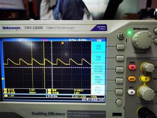
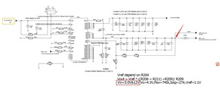
Input voltage 5V, switching frequency setting of 745KHz, expected output voltage 4.3V, but the voltage is like the wave 1 below( The test points are shown by the red arrows in the schematic), the inductance whistles.
VOUT=Vref*((R208+R211+R209)/R209)=1.1* ((26.1K+3.3K+10K)/10K))=4.3V;
Below is the schematic, could you please help give some suggestions? Thank you!
Regards,
Ivy

  • Hi Ivy,

    The second design is most likely bumping into the minimum off-time specification for the the TPS543B20. The typical spec for the minimum off time is 250ns. Without factoring in the DCR of the inductor, I calculated the minimum off time of the 5Vin to 4.3Vout design to be approximately 178ns, which is beyond the limitations of this controller. 

    In order to combat this, I would recommend reducing the switching frequency and increasing the inductance if possible. This will increase the switching period such that the controller may meet its minimum off-time requirement and increasing the inductance can help reduce the inductor ripple current increase that comes with a switching frequency reduction. 

    Regards,

    Alec Biesterfeld

  • I Alec,

    I got it. Thanks a lot!

    Regards,

    Ivy