Hello friends at TI,
I am designing a 12 cell battery management system for the RIT Electric Vehicle Team and would like to verify that the math below makes sense and is okay to use. I am really only asking because in slauu81 the balance resistors were a magnitude larger resulting in much lower balancing currents. I can't think of a reason why balancing at higher currents would be a problem besides heat. Are there other things I should be careful for besides heat when designing a system to balance at this much higher rate?
For the rest of the balancing circuitry it is essentially the same as the reference design. Most of this is excerpt from the BMS design document I am writing so hopefully it makes sense but yes I am aware I expand lots of basic stuff!
Balance Resistor Calculations
These calculations were done to determine the resistance and power rating required for our balance resistor. To start, the balance current was solved for using the equation below. The percent state of charge imbalance was determined from tests ran on similar chemistry cells the team had available. The resulting percent state of charge imbalance, 2.4 percent, has been used in through the calculations below but other percent state of charge imbalances were explored in a table.

From the balance current and the nominal voltage of the cell, ohms law was used to calculate the proper resistance value for the balance resistor. The max cell voltage is used rather than the nominal cell voltage here because our current balancing algorithm balances only when a cell reaches full charge. This however will likely not remain true for our final balancing algorithm so the balancing current and power dissipation below can be considered the max balancing current and max power dissipation.
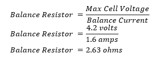
A calculated optimal resistor value of 2.63 ohms would give a balance current of 1.6 amps. This however is not a standard resistor value and would be neither cost effective or worth it to get custom resistors. For this reason, the battery management system team decided to increase the resistance of the balance resistor and therefore decrease the balance current.
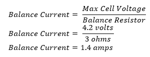
The power dissipation is needed to determine the amount of heat that is produced by the balance resistors. The power that is dissipated from the resistors is lost as heat. As stated previously this is the amount of power dissipation when balancing the cell at max voltage. If the cell was balanced at a lower voltage the power dissipation would be lower.

Each of the balance resistors will produce 4.32 watts of power dissipation when balancing. This can be considered the max power dissipation.
|
%SOC Imbalance |
Balance Current |
Power Dissipation |
Time to Balance |
|
1.4% |
1.2 amps |
4.32 watts |
0.784 hours |
|
2.4% |
1.2 amps |
4.32 watts |
1.344 hours |
|
3.4% |
1.2 amps |
4.32 watts |
1.904 hours |
|
4.4% |
1.2 amps |
4.32 watts |
2.464 hours |
|
5.4% |
1.2 amps |
4.32 watts |
3.024 hours |
|
10% |
1.2 amps |
4.32 watts |
5.600 hours |
|
20% |
1.2 amps |
4.32 watts |
11.20 hours |
Table 2: Three Ohm Resistor at different %SOC Imbalance
It can be observed from the table that no matter how out of balance the battery pack gets, the amount of balance current and therefore power dissipation will remain the same. The resistance of the balance resistor determines the balance current & the power dissipation. Varying the amount of imbalance within the battery pack only changes how long it takes for the battery pack to balance.
The target time to balance the battery pack in was one hour. Assuming the expected percent state of charge imbalance of 2.4%, the system is set to balance in approximately an hour and twenty minutes. This balancing time has been determined to be good for the DEV1 system.
Another Method of calculating current from balance resistor that I think is more accurate and less general
The Internal FET resistance when on is typically 28 ohms. This value was taken from the TI design forums… thanks Terry! To make the calculation above even more accurate the internal resistance of the cell could be included but being that it is likely less than 1 ohm it is not needed. The diagram below shows the path of the current when the internal FET is on.
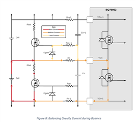
The bulk of the balancing current will flow from the cell and through the balancing resistor being dissipated as heat or going through the external balancing FET. A small amount of current will go through Rn-1, through the battery, through Rn and then through the internal balancing FET. An even smaller amount of current will flow through the diode and Rgn+1. An equivalent circuit can be drawn to determine the exact amount of current through each resistor as seen in the figure below.
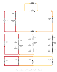
With the schematic simplified down to three parallel resistors the math gets much easier. To simplify the circuitry down it was assumed that the resistance of the diode was negligible compared to the 10,000-ohm resistor that it is in series with.

From the equivalent resistance the total current can be found using ohms law.
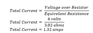
The individual branch currents can be calculated using ohms law. You can see most of the current goes through the external FET and balancing resistor as desired.

This means there will be 1.31 amps flowing through the balance resistor and the external FET with a 3-ohm balance resistor. This also means there will be 1.31 amps flowing through the external balance FET.
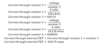
From these calculations the battery management team learned that there would be 0.0179 amps flowing through the internal balance FET. This value is needed to calculate the heat produced by the BQ76952 chip and to keep it under its max temperature.
Both ways of going about calculating the current result in approx. the same value.
Alex Trostle
Electrical Lead
RIT Electric Vehicle Team

