Other Parts Discussed in Thread: TPS62082, , TPS61252
Hi TI Support team,
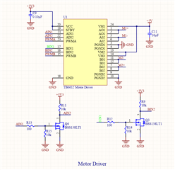
I have designed (PCB produced) a board that will be used to control some sensors (humidity, temperature etc). The board is also designed to drive two DC motors (3-6V, 250 RPM, total max 500mA current under load for two of them) and I used TB6612 as dual motor driver. The motor driver has built in back emf protection.
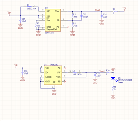
My board has two input sources USB and 1s 2200mAh 18650 Li-ion battery. I am just using USB to program the MCU on the board. The battery voltage is converted to 3.3V through TPS62082 to power MCU and sensors. The battery voltage is converted to 5V through TPS61251 and 5V is only used to power motor driver IC. There is no problem regarding 3.3V. In my previous board, voltage input was 4xAA battery and I used MC33063 to get 5V and power Motor driver and other sensor and MCU part and the PCB worked well.
I have problem regarding 5V. When I check the voltage on 5V out of TPS61251 it is ok. But when I connect it to motor driver IC (0 ohm jumper) and drive motors two or three times (for short time), there becomes short to ground on 5V part. When I replace the tps61251 IC with new one, it is again ok and motor works for some short time, but then short to ground again occurs.
1. My first question is whether TPS61251 is suitable to power motor driver IC? And as I see there is stock problem regarding this component, could you please offer me, a new IC that can be used for my 5V part? I used TI web search for IC selection but not sure if I will see same problem on my board?
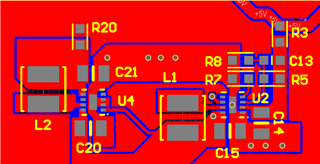
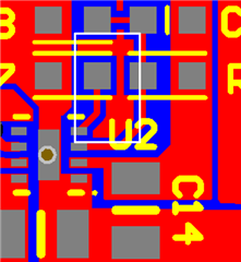
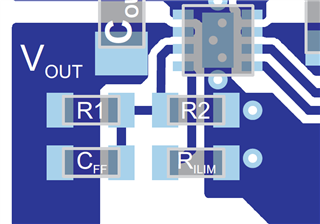
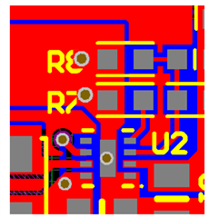
2. The component placement on my board for TPS61251 is very similiar to datasheet PCB layout part. My PCB is two layer, bottom gnd and top 3.3V. I attached the schematic and PCB placement. If the problem is regarding my PCB design could you please comment on it?
Thank you for your help,
Ahmet
