This thread has been locked.

If you have a related question, please click the "Ask a related question" button in the top right corner. The newly created question will be automatically linked to this question.

TPS3850-Q1: Design with MCU and startup trouble

Part Number: TPS3850-Q1
Other Parts Discussed in Thread: TPS3850

Hi guys.

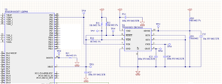
I would like to use the TPS3850-Q1 for:

1) monitor the MCU power supply voltage (overvoltage and undervoltage)

2) une an external watchdog controller

I have only one power supply for all circuits (MCU, TPS3850-Q1 and others): 3.3V.

The microcontroller (STM32F103) does not have the NMI pin; it only has the RESET pin (NRST).

Is the schematic in the picture attached correct?

Can you explain to me how the TPS3850-Q1 works at startup, when power is applied to the board?

How do the WDI and WDO pins behave at startup?

Thanks!

Gabriele.

  • Hi Gabriele,

    This is a good question. When I click the image that you shared, it is blocked on the internal web, can you re-share the image as an attachment to this thread here?

    Thank you,

    Jake

  • Hi Jake.

    I can view the image.

    Therefore I attach here the link to the image: https://ibb.co/jz13Qzv

    Gabriele.

  • Hey Gabriele,

    I appreciate you reposting the image, but unfortunately I still cannot view this. Would you mind using the tools built into this thread to attach the image? At the bottom of the reply box there is an 'insert' tab that allows for the attaching of images directly to this thread without the need of an external website.

    Jake

  • Hi Jake.

    Sorry for the delay but I'm very busy in these days.

    You can see here the image attached below.

    As you can see, SET0 and SET1 are tied to GND together. With this configuration che watchdog timer is enabled.

    Do you think it could work or not during startup? The voltage that I have to monitor is the 3.3V that supplied the MCU.

    I have another question. The MCU doesn not have the NMI pin.

    In my design I connected the WDO and the RESET pins of the TPS3850 together bringing them to the NRST (RESET) pin of the MCU. Is it correct?

    Thank you.

    BR,

    Gabriele.

  • Hi Gabriele, 

    As you can see, SET0 and SET1 are tied to GND together. With this configuration che watchdog timer is enabled.

    Yes, with this configuration the watchdog timer should be enabled.

    Do you think it could work or not during startup? The voltage that I have to monitor is the 3.3V that supplied the MCU.

    It can work during startup. One thing to keep in mind is the state of the RESET pin, as per the datasheet: 

    "WDO only asserts when RESET is high."

    In my design I connected the WDO and the RESET pins of the TPS3850 together bringing them to the NRST (RESET) pin of the MCU. Is it correct?

    Refer to the datasheet regarding the states of the WDO and RESET pins, and whether or not you want to tie them together, as they do have interaction with one another.

    Jake

  • Hi Jake and thanks for your reply.

    The MCU does not have separate NRST and NMI pins. So, I would like to connect the WDO and RESET pins together. In this case the MCU can reset both in case of over/under voltage through the RESET pin and in case of watchdog controller event through the WDO pin.

    What do you think?

    Could you suggest me how the MCU should behave during startup with SET0 and SET1 tied to GND together?

    I am afraid that the MCU during startup will not be able to start because it has not yet enable the peripheral to transfer the signal on the WDI pin and, therefore, the TPS3850 keeps the MCU in reset state through the low WDO pin.

  • Hey Gabriele,

    The MCU does not have separate NRST and NMI pins. So, I would like to connect the WDO and RESET pins together. In this case the MCU can reset both in case of over/under voltage through the RESET pin and in case of watchdog controller event through the WDO pin.

    What do you think?

    Yes connecting the WDO and RESET pins together is fine, and should function in the manner in which you describe. 

    Could you suggest me how the MCU should behave during startup with SET0 and SET1 tied to GND together?

    I am afraid that the MCU during startup will not be able to start because it has not yet enable the peripheral to transfer the signal on the WDI pin and, therefore, the TPS3850 keeps the MCU in reset state through the low WDO pin.

    This is a valid concern. With SET0 and SET1 tied to GND, this would enable the watchdog timer during startup. One design technique is to, during startup, with additional circuitry, disable the watchdog timer by setting SET0 to 1 and SET1 to 0 during the startup period, then after the startup period, enable the watchdog timer.

    Jake

  • Hi Jake!

    Do you mean that I have to use another chip that feeds SET0 to "1" during startup and that brings it to "0" one the MCU is started?

    Is it mandatory to do or is it possible to avoid adding external components to the TPS3850?

    If this were mandatory (I hope it's not), would you have a circuit or an application notes to suggest to me?

    Thank you.

    Gabriele.

  • Hi Gabriele,

    Depending on the constraints of your system, another chip may or may not be necessary to feed the SET0 to 1 during start up and then back to 0 when the MCU is started. A pull-up resistor to a GPIO is one example of a way of achieving this.

    Jake

  • Hi Jake.

    I'm sorry, but I still don't understand if it is really necessary to boot the MCU with the TPS3850 watchdog funtion disabled.

    Is it mandatory to startup the MCU with the external watchdog deactivated or not?

    Could the MCU possibly fail to boot as it is held in reset by the TPS3850 not receiving the WDI signal from the MCU?

    Let's assume that SET0 to "1" is needed during system startup. In this case I could connect SET0 to "1" with the pull-up resistor to 3,3V. This pull-up would the be bypassed by the MCU once it has started bringing SET0 to "0" in order to enable the external watchdog. The problem is: what happens when the MCU is reset on the NRST pin due to, for example, about the timeout generator on the WDI pin? If I'm not mistaken all the pins are placed in high impedence state when MCU is in reset state. So SET0 would return to "1" and the external watchdog would be disabled. But in this case the WDO output go back to "1" because SET0 is "1" and the MCU return in RUN mode. What do you think?

    BR,

    Gabriele.

  • Hi Gabriele,

    Well I do not know all of the constraints of your system. It may in fact not be necessary, depending on the system design, but then again, it may be. As per the specifications of the TPS3850, the WDO_B pin will assert if it does not receive a pulse within a specified window of time. The window of time is set based on the capacitance on the CWD pin, which in your case is 100nF. This correlates to a ~55ms TWDU and a ~6.8ms TWDL. If the MCU can boot in time, and send pulse to the WDI pin, then it is not necessary to disable the watchdog timer during the booting process, because the MCU will finish booting and it will send a pulse to the TPS3850 in time. 

    Regarding the scenario you described. I believe everything you have written to be accurate. Returning the MCU after a reset to RUN mode may or may not be desirable based on the system design, which depends on how you want the system to perform.

    Jake