Hello All,
I am a student trying to build a LED driver circuit for my project. I am trying to power up the circuit step by step to check for errors. I have a ready PCB with all the components on it. I am trying to see if UC3842 is working properly and gives a output gate pulse of a specific frequency and voltage designed by me.
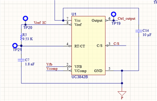
I am powering the IC directly by supplying voltage to the VCC and GND pins. I have connected RT and CT to to generate a frequency of 100kHz. My IC works fine, i.e. once I power it up, I get 5V at the Vref pin, and the RT-CT circuit is also proper, where I get around 95kHz at the RT/CT pin.
When I apply a voltage at the Vcomp pin, I cannot observe any output pulse from the IC (at pin 6). I thought that for the IC to generate an output pulse, or to test it, these components were sufficient.
Am I missing something?
Should there be some more components for me to test the basic working of the IC?
Please Advise.
I am attaching the circuit I have around the Control IC.

I have some other components related to the control loops, but they are located somewhere else on the schematic.
Are these components enough to do a basic operation test of the IC?
Thank you,
Priyankar Vidwans.

