This thread has been locked.

If you have a related question, please click the "Ask a related question" button in the top right corner. The newly created question will be automatically linked to this question.

LM5156H: Boost Converter is having transient problems.

Part Number: LM5156H
Other Parts Discussed in Thread: LM5155,
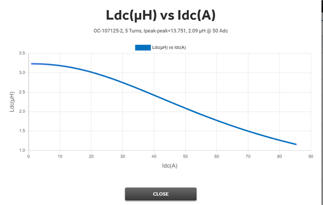
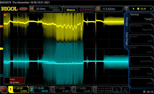
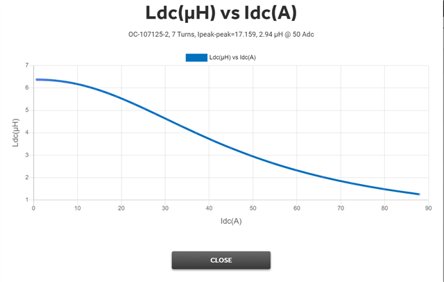
The attached design was created using the LM5155 quick start guide and uses an LM5156H (component selection is skewed heavily by parts availability).  The inductor is a micrometals OC107125-2 with 7 turns of two strands of 13AWG wire.  I attached the inductance vs current profile for the inductor.  The fet is an IPD200N15N3 with an Rdson of 16 mOhm.  I attached the transient simulation results from webench which shows the design I have should produce what are more than adequate results.  In practice, the boost converter exhibits a ~10V drop in voltage followed by a slow recovery when load steps from minimal current to 8 A.  How can I fix this problem?  
Thank you.
Webench Results as a PDF:
  • Hell Neil, 

    Thanks for reaching out. Can you please confirm the specs of your design (Vin, Vout, Iout and switching frequency)? Do you have any scope plot of the load transient that you can share with us? It would be helpful to monitor the voltage on the CS pin as well; in addition, can you please check the values of the RC filter on the CS pin (Rcs1, Ccs)? I'm looking forward to hearing from you. 

    Kind regards, 

    EM 

  • EM, 

    Thank you for your reply. Here is more information:

    Vin = 13-16V
    Vout = 60V
    Lout = 6uH @ 20A, 3uH @ 70A, see the newer plot attached to this post
    Switching frequency = 250 kHz
    CS pin has a 750 Ohm slope compensation resistor, no filter
    Compensation network is 5.8k and 33nF
    Voltage feedback divider is 300k and 5.1k
    Same other components, inductor is two of these in series (actually two cores wrapped together): 
    Here is the voltage measured on the output of the converter driving a motor driver. Yellow trace is the output voltage and the blue trace is the input voltage.
    Thank you
  • Hello Neil, 

    thanks for your reply. As first thing, I would recommend to have an RC filter on the CS pin ( like 100 ohm and 100 pF) in order to filter out spikes caused by parasitic and avoid false current limit triggering. It looks like your VIN as well is not so stable, do you have a plot of the switch node and COMP pin as well? 

    Kind regards, 

    EM