Because of the Thanksgiving holiday in the U.S., TI E2E™ design support forum responses may be delayed from November 25 through December 2. Thank you for your patience.

This thread has been locked.

If you have a related question, please click the "Ask a related question" button in the top right corner. The newly created question will be automatically linked to this question.

UCC28070: With DC input.

Guru 10735 points
Part Number: UCC28070

Hi team,

I refer to the following post.
https://e2e.ti.com/support/power-management-group/power-management/f/power-management-forum/976796/ucc28070-use-ucc28070-with-dc-input/3608367?tisearch=e2e-sitesearch&keymatch=UCC28070%20dc#3608367

My customer wants to use it with DCinput.
It is an application that should only boost the voltage of PFC.
This thread said if the input voltage range is narrow and you do not expect to have input voltage transients in your application then UCC28070 would be ok.
Could you tell me more detail about input voltage transients?
I'd like to know when there is a problem.

Sincerely.
Kengo.

  • Hello Kengo-san,

    As was mentioned in the previous E2Es, the UCC28070 needs AC input to select an appropriate KVFF.  On power up, the controller always starts with KVFF Level 8 (3.857).  Because the DC voltage input doesn't cross zero volts, the KVFF stays fixed at 3.857 (it never gets updated).

    Using EQ(13) to calculate IIMO, substitute your scaled VINDC for VINAC (see table 1) and 5V (worst-case max) for VVAO. RIMO can then be calculated to provide the desired IIN(PK) based on this fixed IIMO

    Using the fourth column in table 1 as a guideline for the range that Vin falls within each KVFF level (say 20-30V), if VINDC is expected to vary by 10V or less, the variation should be acceptable.  If VINDC is expected to vary by 30V or more, then this would require a more in-depth analysis.  Of course, any input voltage transients would need to be added in to your expected VINDC  variation.

    I hope this helps to clarify.

    Ray

  • Hi Ray-san,

    Thank you so much for your reply.

    In your comment, does Kvff calculate based on VINAC's 0V?

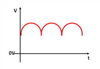
    Does it mean that the below full-wave rectification cannot be input?


    Sincerely.
    Kengo.

  • Hi Kengo-san,

    The rectified information is used to wave-shape the A/C sinusoidal input current to match the actual (unrectified) A/C sinusoidal input voltage.  That is where the zero-volt-crossing information is derived.

    Regards,

    Ray

  • Hi Ray-san,

    Thank you for your reply.
    In other words, does it mean that KVFF is calculated and operates without problems even if there is no voltage of 0V in VACIN?

    Even if there is no 0V cross information, is there any problem if the voltage changes like AC?

    Sincerely.
    Kengo.

  • Hello Kengo-san,

    As I stated earlier, KVFF is NOT updated if there is no zero crossing on the input.  It will remain fixed at the initial (and highest) value of 3.857.

    Again, if there is no zero voltage crossing, there will be problems if the voltage changes (including input transients) beyond several tens of volts.

    Ray

  • Hi Ray-san,

    Thank you for your answer.
    I understood what happens if the input is no zero crossing.

    I'd like to know about the problems if the voltage changes.
    Could you teach me?

    Sincerely.
    Kengo.

  • Hello Kengo-san,

    A DC input voltage, as we discussed, will not allow the controller to update the Kvff.  If this VIN(DC) changes enough such that the controller would otherwise want to change the KVFF range in order to scale IIMO accordingly, IIN(rms), IIN(pk) and PIN(max) will not maintain their scaled, expected values.

    I don't think I can reduce it down more than I attempted to above.  I believe sec 7.3.10 of the datasheet describes the function of the QFF function rather thoroughly, but please let me know if you still have questions on this and I will do my best to clarify.