This thread has been locked.

If you have a related question, please click the "Ask a related question" button in the top right corner. The newly created question will be automatically linked to this question.

TPS81256: TPS81256 PFM/PWM Load Transition Point

Part Number: TPS81256
Other Parts Discussed in Thread: TPS7A84A, TPS61027

Hi TI Support,

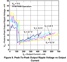
We are considering the TPS81256 for an Bluetooth audio application, but are concerned about the PFM feature generating noise within the 20kHz audible range, as well as the increased ripple associated with this mode of operation.

Our power source is a single-cell Li-Ion battery, 5V output of the TPS81256 will be fed into a 3.3V LDO regulator to power all internal circuits. Our circuit presents a dynamic load of between 10mA to 40mA @ 3.3V.

After carefully reviewing the data sheet, we can't find information on the transition point between PFM and PWM operation; it is only stated that PFM operation is used under light loads.

Any advice of information you can provide us will be greatly appreciated.

With best regards,


Claudio

  • Hi Claudio,

    Thanks for reaching out. The threshold between PWM/PFM is about 100mA~150mA. The Figure 9 in datasheet has specified this.

    For your case, the PSRR of the LDO is important. Taking TPS7A84A as an example, it has >50dB PSRR for 20kHz noise, so it can compress the noise to 1/316 of original value. This means if TPS81256 has 30mV pk-pk, it can compress the noise to 95uV.

    -Wenhao


  • Hi Wenhao,

    I sure missed that detail on the data sheet, thanks for highlighting it ! It looks like in the case of our application, the part will constantly operate in PFM mode.

    We had a similar situation a few years back with a different design using the TPS61027. Because of our circuit loading conditions, the part also operated in "power save" mode. In that case, the inductor used generated some undesired audible noise, and the output voltage had increased ripple and impulse noise (high freq) that was hard to eliminate even after the LDO stage. That hf noise was present in our audio output as well. The solution on that design was to disable the "power save" mode via the PS pin (pulled to High).

    We are concerned about facing the same issues while using the TPS81256, since there is no way to disable the PS mode on this part. Careful selection of the LDO to take advantage of high PSRR will definitely help to decrease the output ripple, but it is trickier to diminish impulse noise at the output. This high frequency noise is a concern because of the audio nature of our application. 

    Due to the miniature size of the TPS81256 circuit, I am assuming audible noise form the on-board inductor will be significantly less, if any. Do you have any feedback for us in this regard?

    We will reconsider our LDO selection, looking for a part with better PSRR. Should we consider use of a ferrite bead between DC/DC and LDO to manage any impulse noise that might be present at the output? Any advice you might have on this area will also be very useful.

    We are expecting a TPS8125xEVM board later this week to investigate this part further.

    Thanks once again for your quick response to our request, with best regards


    Claudio

  • Hi Claudio,

    Due to the miniature size of the TPS81256 circuit, I am assuming audible noise form the on-board inductor will be significantly less, if any. Do you have any feedback for us in this regard?

    [WW]I am not sure about your load current in normal case. You could use EVM to evaluate it.

    We will reconsider our LDO selection, looking for a part with better PSRR. Should we consider use of a ferrite bead between DC/DC and LDO to manage any impulse noise that might be present at the output? Any advice you might have on this area will also be very useful.

    [WW]Regarding low frequency noise, LDO is better than ferrite bead as ferrite bead has stronger effect for frequency band of MHz.

    -Wenhao