This thread has been locked.

If you have a related question, please click the "Ask a related question" button in the top right corner. The newly created question will be automatically linked to this question.

BQ27421-G1: Bq27421yzfr-g1d is abnormal

Part Number: BQ27421-G1
Other Parts Discussed in Thread: BQ27426

Hi  Ti engineer ,

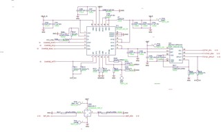
1.At present,  Six anomalies have been detected in BQ27421YZFR-G1D,After D21, the output is only about 0.4V, that is, D21 pin C3 is the battery voltage, C2 is only about 0.4V, please ask whether there is any abnormality in the schematic diagram below, and what may be the cause of the failure?  

2.Software:

Platform: Android 4.3

Chip: BQ27421

The driver is downloaded from the official website and can read and write registers normally after 4.3 adaptation.

The current battery Settings are as follows:

static struct bq27xxx_dm_reg bq27421_dm_regs[] = {
        [BQ27XXX_DM_DESIGN_CAPACITY]   = { 82, 10, 2,    0,  4300 },//8000
        [BQ27XXX_DM_DESIGN_ENERGY]     = { 82, 12, 2,    0, 16568 },//32767
        [BQ27XXX_DM_TERMINATE_VOLTAGE] = { 82, 16, 2, 2800,  4200 },//2500 3700
};

static void bq27xxx_battery_settings(struct bq27xxx_device_info *di)
{
        struct power_supply_battery_info info = {};
        unsigned int min, max;

        //if (power_supply_get_battery_info(di->bat, &info) < 0)
        //      return;
        info.energy_full_design_uwh = 16568000;//7700;
        info.charge_full_design_uah = 4300000;//2100
        info.voltage_min_design_uv = 3300000;//3700
        //info.precharge_current_ua = ;
        //info.charge_term_current_ua = ;
        //info.constant_charge_current_max_ua =;
        //info.constant_charge_voltage_max_uv = 4350;
                ...
}


Please help confirm:  

1. How to adjust the battery adapter  

2. Check whether the read value of the register is normal  

temp = 3121, volt = 4181, NAC = 3483000, FAC = 3483, RC = 3450000, FCC = 4122000, AC = 0, SC = -5, MaxLoad = 65280, AP = 0, soc = 84, dcap = 4300000, health = 1

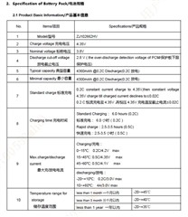
Below are the battery specifications:


  • Please attach the schematics.

  • >the output is only about 0.4V, that is, D21 pin C3 is the battery voltage, C2 is only about 0.4V

    There's a metal layer sense resistor between C3 and C2 inside the bq27426 which is internally connected to the coulomb counter delta sigma ADC via high impedance traces. The resistance is around 10mOhm so if C3 is the battery voltage (e.g. 4V) and C2 is 0.4V then there would have to be a current of about 3.6/0.01 Ohm = 360A, which is extreme and way outside the max. operating conditions of the gauge (SRX is abs.max (=damage limits) BAT +/- 0.3V).

    So if this is indeed what you are measuring then the internal sense resistor has burned out (e.g. the abs. max. was violated in the past). The schematics don't contain enough information to say. What's the max. current between SRX and BAT1/2 from the other IC on this design? Make sure that it's less than the limits from 7.10 Integrated Sense Resistor Characteristics, –40°C to 85°C in the d/s

    About your second question:

    The gauge uses 16-bit integers for capacity results so it's not possible for the gauge to return FCC = 4122000. Please verify that the driver reads this correctly (the driver is not maintained by TI). For example, FCC is a simple little endian 16-bit unsigned integer available from I2C registers 0x0E/0x0F, units are [mAh]

    Make sure that you used the instructions from https://www.ti.com/lit/ml/sluuah7b/sluuah7b.pdf when configuring the gauge. You must run a learning cycle (discharge, relax 2 hours, charge, relax 2 hours, discharge C/5, relax for 2 hours) before gauging becomes accurate. If that isn't possible, it'll take a few cycles for the gauge to learn the cell's properties in your system.