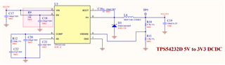
Hi Team,
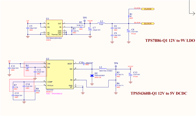
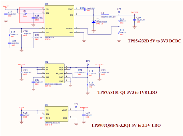
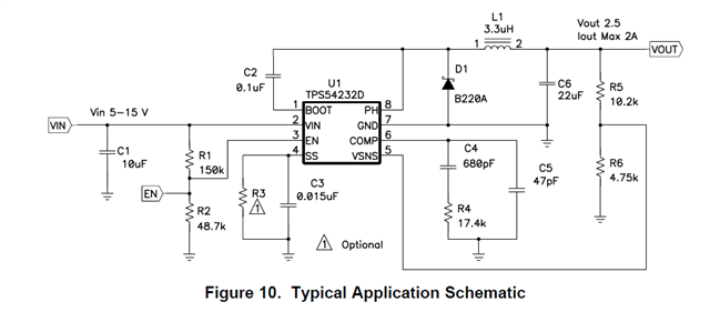
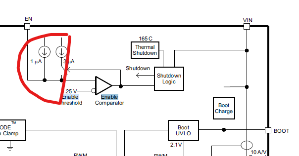
There is a good new that we DIN TPS54232
And there have one thing need your support!
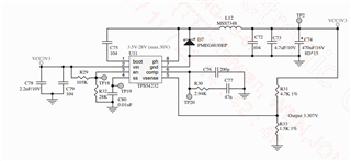
Please help check this SCH, THX
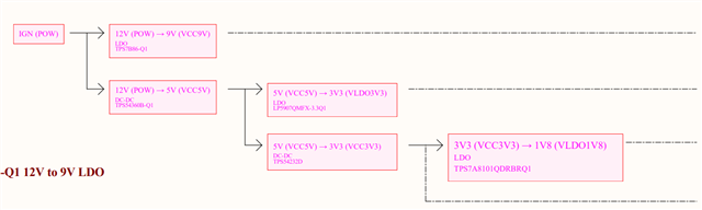
Hi Team,
There is a good new that we DIN TPS54232
And there have one thing need your support!
Please help check this SCH, THX