Hi,
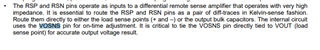
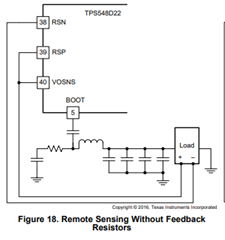
In the TPS548D22RVFR buck converter, We are using the output voltage set by VSEL(pin number 33) pin of TPS548D22RVFR, As per the datasheet VOSNS, RSP connected to the output and RSN connected to Load return,
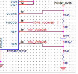
We have simulated the same in the webench that shows the VOSNS connected output, RSP connected to the output with 10E, and RSN connected to load return with 10E,
As per this recommendation, we need clarification on the layout routing of the 3 nets VOSNS, RSP, and RSN also the placement of the two10E resistors
We have planning to place the two 10E resistors at the load side, the capacitor at the module side, and rout the 3 nets(VOSNS, RSP, RSN) from the load side. please find the image
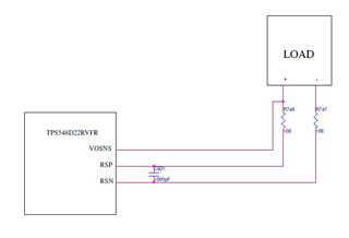
Please confirm is this correct or not otherwise please suggest the best method for routing.