A related question is a question created from another question. When the related question is created, it will be automatically linked to the original question.
If you have a related question, please click the "Ask a related question" button in the top right corner. The newly created question will be automatically linked to this question.
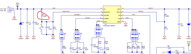
I didn't know which one of the component is short circuited. When tested, Ch1 did have the appropriate value for Vin but for Vout the value is lesser than it's supposed to be. I am guessing it's short circuited. I did modify the circuit by desoldering R1 from the board.
I also tested other components aside from the eFuse with voltmeter to see if they aren't functioning, but they were fine. I couldn't figure out how to test if the eFuse is functioning or not. Could you tell me the way to test?
Have you connected any load at output? How much is VIN and VOUT? You can remove eFuse from PCB and measure impedance between its pins VIN-VOUT,VIN-GND,VOUT-GND. Also you can measure impedance on PCB pads for this device.
But one thing if you desolder R1 device will disable, EN pin will be GNDed. Any other modification you did?
You can remove eFuse from PCB and measure impedance between its pins VIN-VOUT,VIN-GND,VOUT-GND. Also you can measure impedance on PCB pads for this device