This thread has been locked.

If you have a related question, please click the "Ask a related question" button in the top right corner. The newly created question will be automatically linked to this question.

TPS7A94: About VFB_PG

Part Number: TPS7A94

Hi, support team

My customer has the questions as follow:

In my design: input VIN = 2.5V, output VOUT = 1.8V, ICL = 80%

1. Which value should I choose for VFB_PG(typ) in Equation 3 when I calculate RFB_PG(TOP) and RFB_PG(BOTTOM) according to Equation 3?
0.2V? or 0.21V? or (VIN-VDO)~0.2V in Note1?

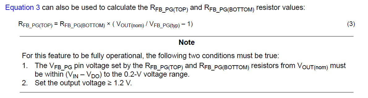
2. How is the PG threshold parameter calculated in table 9-1?


Thanks so much.

Best regards,
Yuki

  • There is one more question:

    3. What is VEN_UV(HI) and VEN_UV(LOW) value?

    Thanks so much.

  • Hi Yuki-san,

    1. The middle column is the typical value, so in this case you would use 0.2V. You can also use the min and max V_FB_PG specs to calculate the min and max PG threshold.
    2. I'll use the VOUT(nom) = 5.1V last row case as an example. The V_FB_PG voltage when VOUT = VOUT(nom) is V_FB_PG = 5.1V * 100kΩ / (100kΩ + 2322kΩ) = 0.2105V. The PG trip point is 0.2V (typ), and so the PG threshold is then 0.2V / 0.2105V = .95 = 95% (typ) of the nominal voltage. 
    3. The specs are called V_IH(EN) and V_IL(EN) in the EC table. We will need to update the datasheet to keep a consistent naming convention. Thank you for bringing this to our attention. 

    Regards,

    Nick

  • Hi Nick,

    Thanks so much for your kindly reply.

    About the third question:
    In Figure 9-20, VOFF=3.75V, VON=4 V, Rtop=1.54 MΩ, Rbottom=100KΩ.
    According to Equation 2, VEN_UV is not higher than V_IH(EN) ?

    Thanks so much.

    Best regards,
    Yuki

  • Hi Yuki-san,

    Yes that looks like another error. I calculated the R_TOP to be 212.5kΩ for this application. Does that sound right?

    Regards,

    Nick