This thread has been locked.

If you have a related question, please click the "Ask a related question" button in the top right corner. The newly created question will be automatically linked to this question.

LM5180: Regulation intermittently switching off while driving dual output +15/-8V for IGBT gate drive power supply

Part Number: LM5180

Hello,

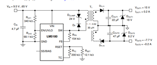
I am seeing an intermittent stop of the switching output on our gate driver board. Our use case is pretty much "9.2.2 Design 2: PSR Flyback Converter With Dual Outputs of 15 V and –7.7 V at 200 mA" from the datasheet.

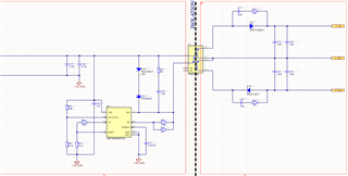
The schematics is as follow (input voltage is 24V, coming from a Traco 24V DC-DC, I've scoped Vin and it is fairly steady and noise free):
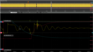
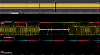
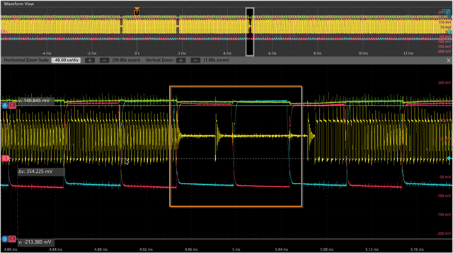
We are seeing the following intermittent behaviour when the gate are switching:

(Green = SW output from LM5180, Red/blue = Low/High side gate Vgs)
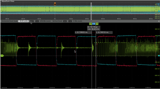
You can see on the zoomed out plot at the top of the pictures the interruption is quite severe.

We've somehow managed to reduce/remove the behaviour by adding a Y cap between the isolation barrier, but we do not think this is a "proper" fix and would like to understand what is causing the PSU to stop regulating.

The main problem is that we think this has in time caused some IGBT failures (after only 1h of running!). The Vgs voltage not being high enough (potentially 10-12V instead of 15V) is causing the switches not to turn on fully, increasing dissipation and ultimately making the switch fail. Some times, the regulation stops long enough for the gate driver UVLO protection to trigger.

Thanks for your help,

Quentin.

  • Hi,

    I notice that the output capacitor for your schematic is different compared to the one shown on the datasheet. 

    Is it possible to increase the output capacitor per datasheet recommendation?

    Thanks

    -Arief

  • Thanks for the suggestion. We've tried this already and it doesn't really help. There is also some extra capacitance at both the gate driver and the booster (about 10uF for each), so there's more than the 20uF shown in this part of the schematics.

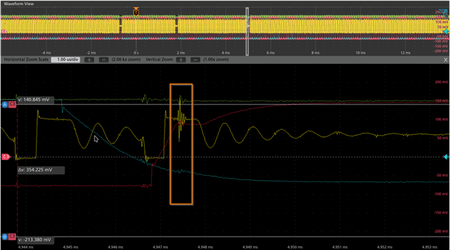
  • Here are a couple more screenshots, with the +15V rail on the scope:

    The first one shows that the regulation stops when the Switching pulse happens at the same time as the High-side switch turns on:

    (Yellow = SW, red = Vgs). You can see it happens right at the miller plateau on the red signal, when the voltage reaches the turn-on voltage.

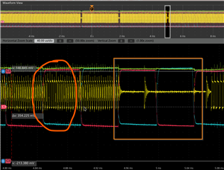
    Second screenshot is a zoomed out picture that shows the impact on the +15V rail:

  • Hi Quentin,

    When i look at your second picture of no switching section, it is as if there is no load at the output and no current flows and the converter reduces it switching frequency. 


    is there a way to measure the current coming out of the output of the 15V rail? This just to make sure the circuit is not overloaded beyond 0.2A.

    I also noted a perturbation on the switching waveform at that miller plateau. 

    Can we take a look at your layout for the LM5180? A localized decoupling capacitor near the gate driver may be needed to make sure such that the noise is isolated. 

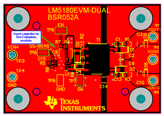
    We also have an evaluation module for your specific condition. Just for testing, you can also try to use the evaluation module to power up your gate driver and see if it behaves the same. Since the noise perturbation on that SW node during miller plateau may couple back in to FB pin. 

    https://www.ti.com/lit/ug/snvu609b/snvu609b.pdf?ts=1638906661521&ref_url=https%253A%252F%252Fwww.ti.com%252Fproduct%252FLM5180

    Thanks

    -Arief

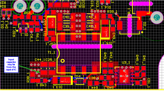
  • Here is the layout, there isn't a lot of space as we're on the edge of the board.

    About your comment about the PSU going into FFM, I had the exact same thought yesterday. This is pretty unlikely as this always happens right after the gate turns on, which is where most of the power is being used. At that moment, both gate driver and boosters will have charged the gate. You can see it on the previous cycle in the screenshot, at the moment the SW output is almost in BCM.

    We also think that perturbation near the miller plateau is what is causing that interruption in the control.

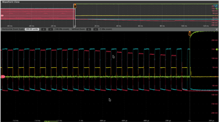
    We have a very rare case where the regulation stops for a very long time, and it ends up triggering the gate driver UVLO as the +15V drops way too low:

    this screenshot is only showing the High/low side Vgs, but we suspect the same thing is happening.

    Keep in mind all this testing is done with a Vdc of only 100V, the behaviour is likely to get much worse at the 350-400V we typically use when driving the motor.

  • Hi Quentin,

    One thing that i noticed is that your input capacitor is located quite far away from the IC. Therefore the return current from the input capacitor back to the internal FET ground is long. 

    Comparing to the EVM routing of the input capacitor

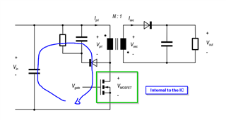
    The loop from input capacitor, through the transformer and GND of the IC is quite important and we need to make the loop small since that is a switching loop on a flyback converter. 

    You can try to put a ceramic capacitor between pin 3 and 8 or 9 and see if it is improve your regulation. 

    Is your board 2 layer or 4 layer?

    Another test that you may be able to do is to load the converter with a resistive load and make sure that it can support a DC load of 200mA and make sure that the +15V and -7V rail is well regulated with the DC load. 

    If that looks ok then the next step is to connect the gate drive, from the scope shot that you sent, the perturbation on the SW node seems a bit large.and may cause some misbehavi]ng

    Thanks

    -Arief