


Hi,
We are doing an ECO and all DC-DCs have been re-layouted. All high-current parts are on TOP and the feedback resistors are on bottom. We connected the feedback resistor directly with VIAs in pad on output capacitors without small traces.
1) Is-it OK? Or we need to have feedback resistors connected to a less noisy area? I know that LC area have high freq current. I am not sure if it can affect the feedback.
Inside the following picture:
RED = TOP
BLUE= BOTTOM
Yellow rectangle: Vias in PAD to connect the feedback resistors.
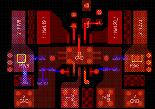
2) Same questions for the feedback pin (pin 4) of the 1st DC-DC.
3) I am not sure why this DC-DC has a separate feedback pin (pin 4) vs resistor divider pin (pin 5). I never saw this on others DC-DCs. Can you explain me purpose of this feedback pin vs voltage divider?
Thanks,
Denis Alain, Eng
