This thread has been locked.

If you have a related question, please click the "Ask a related question" button in the top right corner. The newly created question will be automatically linked to this question.

BQ2057C: VCC short issue

Part Number: BQ2057C
Other Parts Discussed in Thread: BQ21040

Hi team,

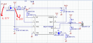
Using the BQ2057CDGKR, set the 6.67 mA charge current, test the discharge time and find that the battery output is 0V, that is, disconnect the battery to disable the battery discharge, and recharge the battery again. A short to VCC was found due to a short in Q1:
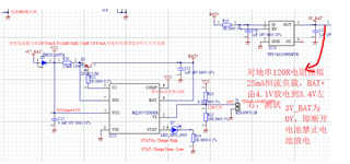
(Please be noted that the Chinese in the figure means: The maximum charge current is 20-50 mA, 2mR-5mR. It takes about twelve hours to fully charge. Test the string 120R resistor to simulate a constant 25-mA load, and BAT+ is discharged from 4.1 V to around 3.4 V. 3 V_BAT is 0 V, which disables battery discharge by disconnecting the battery. )

The customer would like to know is the battery charged and discharged all through Q1?

The 25-mA discharge does not short Q1 because the thermal power consumption of this chip is not exceeded.
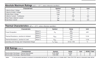
Could you help check this case? Thanks.

Best Regards,

Cherry

  • Hi Cherry,

    I'm looking into this you can expect to hear back by 12/16.

    Thanks,

    Nick

  • Hi Nick,

    Noted and thanks for your support here!

    Here's also an additional question:

    Is the BQ2057C and BQ21040 discharge current determined by the load or anywhere can set it? Can BQ2057C use NPN? Must use PMOS?

    Thanks and Best Regards,

    Cherry

  • Hi Nick,

    Here's some updates:

    The BQ21040 document mentions that it supports for a minimum offset current of 10 mA, but the recommended range is 50 mA-800 mA.

    If in order to use this tubless charge management chip, but the maximum charge current of the 4.2-V Li-ion battery is 20 mA, is it possible to set the charge current between 10 mA and 20 mA using BQ21040? Or could you recommend a charge management chip for a 4.2V Li-ion battery with no external tube?

    Also, charging 4.2-V Li-Ion battery with BQ2057CDGKR at a voltage between 4.7V and 5.3V can only be charged to 4.1V.  Is it ok? Or is there anything wrong with the design?

    Thanks and Best Regards,

    Cherry

  • Hello Cherry,

    Using the BQ2057CDGKR, set the 6.67 mA charge current

    Can you confirm whether they are using a 15 ohm or 15 mOhm resistor for this setting correct? The schematic shows 15 milliOhm if I'm not mistaken. If they are actually using a 15 mOhm resistor this is setting the charge current to 6.67A which might be seen as a short through Q1...

    20-50 mA, 2mR-5mR

    I believe you also mean 2- 5 ohm? You can refer to the equation is listed on datasheet page 10. 

    The customer would like to know is the battery charged and discharged all through Q1?

    The battery should only be charged through Q1, not discharge. Recommend adding D1 from schematic here to ensure no reverse current flow from battery to input: www.ti.com/.../sluu056a.pdf

    We ask that you kindly make a separate post for the bq21040 questions.

    Thanks,

    Nick

  • The charging voltage for bq2057C can be as low as 4.158V, 4.1V does seem low. Are they measuring directly from the BAT pin? This is where IC takes the measurement. Are they allowing the battery to discharge before measuring the max charging voltage?

    Thanks,

    Nick

  • Hi Nick,

    Thanks for your support!

    Can you confirm whether they are using a 15 ohm or 15 mOhm resistor for this setting correct?

    Yes, they are using a 15 Ω.

    The battery should only be charged through Q1, not discharge. Recommend adding D1 from schematic here to ensure no reverse current flow from battery to input: www.ti.com/.../sluu056a.pdf

    For the schematics, they have replaced it to D1-ZHCS1000TA.

    Are they measuring directly from the BAT pin? This is where IC takes the measurement.

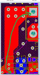
    Yes, they directly measure from the BAT pin, the voltage is 4.1V, but due to space constraints, the BAT pin is routed through the copper to the battery socket, please see figure PCB:

    Are they allowing the battery to discharge before measuring the max charging voltage?

    Indeed they got the battery which has been discharged to 3.9 V from the agent.

    Even if the battery was already discharged before use, is there anything needed to be aware of?

    And is it necessary to use power resistor here? Is it ok to use a common thin film resistor?

    Thanks and Best Regards,

    Cherry

  • Hi Nick,

    The latest update is as follows:

    Changed the resistance to 10 ohms (10 mA) to charge, 4.185V at the end of full charge.

    Thanks and Best Regards,

    Cherry

  • And is it necessary to use power resistor here? Is it ok to use a common thin film resistor?

    They are charging at quite a low current so thin film is likely OK.

    Changed the resistance to 10 ohms (10 mA) to charge, 4.185V at the end of full charge.

    This is within our datasheet spec.

    Thanks,

    Nick

  • Hi Nick,

    Thanks again for your support. Sorry to bother you again. The end customer has some additional questions:

    1. With a charge current of 10 mA, a charge voltage of 5.3 V or 4.8 V, the card needs less than 37 mA when charging, and 6 mA after charging. Is t possible to reduce the current required for charging by setting the charge current low? They have to limit the charge current to 20 mA, is there any way to achieve this?

    2. This board uses a 3.3-V boost chip. Both the charging chip and the LDO are TI (plus a locally produced charge protection chip, which consumes 4 uA). The board is specifically selected for low-power chips. However, the board only operates with these 3 chips and the domestically produced charge protection chip. Board power consumption 11 mA, design issues or power consumption that the chip should operate?

    3. When setting up Rsns10 ohm charging, this board consumes 37 mA. Why is the power consumption not 11mA+10mA at this time, is there a problem with the charging current setting?

    4.Customer requests 20 mA when charging, where can I save power? Does replacing the NPN-DSS3515M with the PMOS-SiA447DJ save power?

    Thanks and Best Regards,

    Cherry

  • Hi Cherry,

    BQ2057C is a very old device, low power efficiency, especially at low charge current settings. How are they measuring the current consumption of the charger in this case? If there are other devices on the board these need to be isolated to get an accurate iq for the charger. Customer can use the FET configuration as seen in Figure 4 to save power yes.

    BR,

    Nick

  • Hi Nick,

    Now they have made some tests:

    1. 2.49 mA charge (2 mA not possible) is set, load is disconnected, only BQ2057C is operating, 4.87V is supplied, please see the figure below. At this point, the power consumption is 9 mA;

    2. If 2.49 mA charging is set, the board consumes 19 mA of power to meet the design requirements;

    3. Is it possible to reduce this portion of power consumption by switching D5 from NPN-ZHCS1000TA to PMOS-sia447dj?

    And also the customer would like to know is there a chip can meet these requirements: charge management chip for 4.2V Lion battery, charge current > 2mA.

    Customer can use the FET configuration as seen in Figure 4 to save power yes.

    And do you mean the Figure 4 in data sheet?

    Thanks and Best Regards,

    Cherry

  • Hi Nick,

    Just a quick updates: now NTC uses a normal negative temperature coefficient thermistor. Could you also please elaborate what is the advantage of the BQ21040 recommending 10K NTC 103AT? Because NTC is on the board, not in the battery PACK.

    Thanks and Best Regards,

    Cherry

  • Hi Cherry,

    And do you mean the Figure 4 in data sheet?

    Yes figure 4 of the datasheet.

    Could you please make a new thread for the bq21040 questions, thanks.

  • Hi Nick,

    Sorry for the misleading description, indeed they are asking regarding the BQ2057C, what is the difference between the common thermistor and the 103AT used by the BQ2057C? 

    Thanks and Best Regards,

    Cherry

  • Hi Cherry,

    Sorry for the delayed response.  The semitec 103AT is a common 10k NTC that works well with our chargers. Customer is OK to use a different kind as long as its the same resistance (10k) and similar beta value ( 3435 K over 25- 85C)

    Best regards,

    Nick

  • Hello Nick,

    The original issue has been resolved now, and here's an additional question(please let me know if it is needed to ask the customer to create a new thread about the new issue):

    The customer would like to know if this chip can use a 2-layer board? At 20 mA of charge current, it causes 3.3 V to rise approximately 0.1 V after being turned on through BAT54C. Is it need a cleaner whole layer of ground? Or use a 4-layer board?

    Thanks and Best Regards,

    Cherry