This thread has been locked.

If you have a related question, please click the "Ask a related question" button in the top right corner. The newly created question will be automatically linked to this question.

TPS65154: IC outputs 0V on all regulators after EEPROM flash and a few power cycles

Part Number: TPS65154

We have a design which is using the TPS65154 for an LCD bias circuit. We are able to flash the IC over I2C and get the desired output voltages for all of the regulators. However, after flashing the EEPROM and waiting a significant amount of time (1 minute) before a power cycle, the system works as expected for 2 to 3 power cycles before all voltages go to 0V. The I2C communication is still working and the register values can be written to and read but the output voltages are all 0V (including the LDO output). All I2C communication is monitored with a Saleae logic analyzer and verified that the correct values are being sent to the IC and that an ACK is being sent by the IC.

Anyone else experience this issue or know what the solution might be?

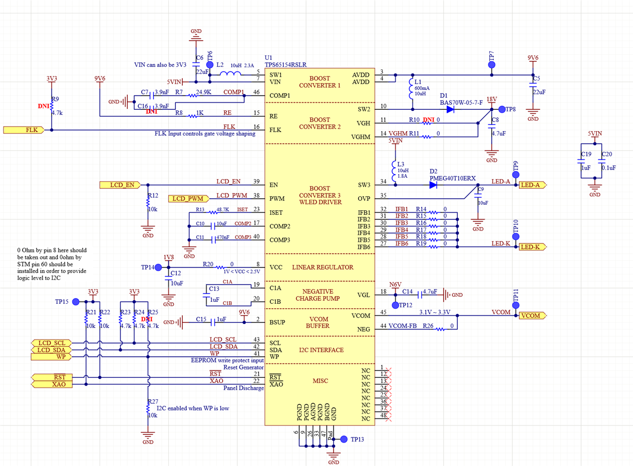
Schematic is below for our board.

Thanks!

  • Hello,

    From the description in your post, it appears that some kind of fault condition like over current, under/over voltage may be happening on one of the output rails of the device. For example, all of the regulator output in this device have a under voltage threshold of 70% of the nominal programmed value and if an over current situation exists for longer than 50ms, the device shuts itself down. I suggest to scope probe the various output and input voltage rails to see what is happening when the device shuts down.

    Kind Regards,

    Liaqat

  • The 0V issue was due to C16 being installed in the compensation network for Boost Converter 1. When C16 was DNI, the 0V issue went away. There is still an issue with the EEPROM. All of the regulator values retain their programmed voltages on power-up except the LDO. As soon as the EEPROM is programmed, the LDO voltage goes to 1V and similarly when the system boots this voltage is at 1V. We have it nominally set to 1.89V. The microcontroller can set all of the voltages as expected and when the display is connected it works. However, the LDO voltage needs to be programmed on powerup vis I2C continuously since it won't save in EEPROM.

  • This is indeed strange that all other regulators retain values but LDO does not retain what was last set in the EEPROM. I don't know why it is like that. Have you tried reading the register 0x01 from eeprom i.e. control register (0xFF) bit 0 is set to a 1 and then read register 0x01 to see if the last written value is read or not? I am just trying to determine if this is an eeprom issue or is it that the LDO register is somehow not read correctly from the eeprom at power up only.

    Do you have more than one board doing this or is it just one board you have tried so far? I am thinking perhaps one faulty device.

    Kind Regards,

    Liaqat