This thread has been locked.

If you have a related question, please click the "Ask a related question" button in the top right corner. The newly created question will be automatically linked to this question.

Question on 54310 compensation network

Anonymous
Anonymous
Other Parts Discussed in Thread: TPS54310

Hi All,


I would like to ask a question on 54310 compensation network.


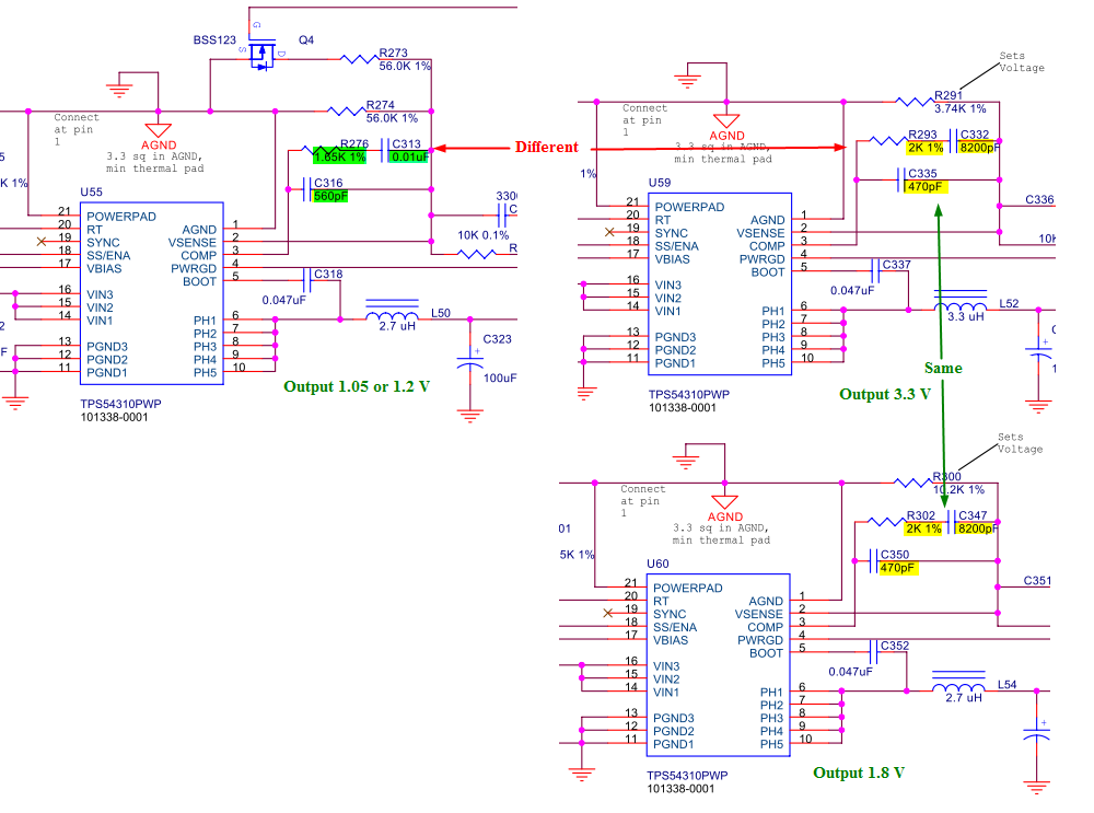
On a design I am referencing (SpectrumDigital EVM6437), I noticed that


Output voltage

Compensation network

1.05 or 1.2V

1.65K, 0.01uF  ||  560pF

3.3 V

2K, 8200pF      ||  470pF

1.8 V

2K, 8200pF      ||  470pF


How are these compensation network components determined?

1.    According to SLVS412d (54310 manual), output voltage is determined by R4 and R5 as in Fig.10 of the manual schematic. So do I still have to adjust compensation network after output voltage is determined/

2.    If different output voltage corresponds to different compensation network, why 3.3V and 1.8V share the same set of compensation network element values? Is there any mistake here?

3.    For 1.05V/1.2V case, after changing (selecting) the output by changing resistor values, does the compensation needs to be changed?


I am bewildered by the large number of equations in SLVA109 - Designing With the TPS54310 Synchronous Buck Regulator, can there be any quick solution on these value determination?


Thanks,

Bob

  • Unfortunately, there is no "easy solution".  The TPS54310 uses voltage mode control with external compensation.  This makes for a very versatile control function that can accommodate  most any type of output filter.  With voltage mode control, the output voltage can be set using just the lower resistor in the resistor divider network.  That resistor is not in the small signal path, so you can change the output voltage without affecting the compensation.  If the output filter is identical, then you can theoretically use the same compensation for any of those output voltages.

    The theory behind closed loop compensation follows general control theory, there are many different approaches that can yield acceptable results.  If you are not familiar or comfortable with them , i suggest you follow the guide lines in the application note you reference.

  • Anonymous
    0 Anonymous in reply to JohnTucker

    Dear John,

    JohnTucker said:

    Unfortunately, there is no "easy solution".  The TPS54310 uses voltage mode control with external compensation.  This makes for a very versatile control function that can accommodate  most any type of output filter.  With voltage mode control, the output voltage can be set using just the lower resistor in the resistor divider network.  That resistor is not in the small signal path, so you can change the output voltage without affecting the compensation.  If the output filter is identical, then you can theoretically use the same compensation for any of those output voltages.

    Which part comprise the "output filter"? Could you explain how it works?


    Zheng

  • The output filter is the inductor plus all of the output capacitors on the output voltage rail of the power supply.  Here are 2 app note that discusses voltage mode control in more detail: http://focus.ti.com/lit/an/slua119/slua119.pdf and http://focus.ti.com/lit/an/slva057/slva057.pdf

  • Anonymous
    0 Anonymous in reply to Chris Glaser

    Dear Chris,

    Thanks for the answer.

    There is a gap between my elementary knowledge in physics and the need to understand this regulator. In the meantime when my board is being soldered and during testing, I wish to try my best to fill this gap.

    Now I am still studying Griffiths's Introduction to Electrodynamics which hopefully can be finished in two weeks. I regard EM theory as a foundation for all electronic stuff and I believe you people should have had these backgrounds. After that junior level EM intro, could you recommend anything that is most relevant to the theory behind voltage regulator, especially switched-mode power supply and/or buck converter?

    I agree that "Nothing could be more practical than a good theory"; on the other hand, for the practical purpose of understanding how regulators work, is special relativity knowledge required? In the operational level, I could do E-M vector calculus with ease as well as most of the standard field/force calculation, but regarding the nature of how EM wave actually propagate in the microscopic level, I still have no clear idea. Some books, such as Griffiths', put relativistic electrodynamics to the end, whereas Purcell's Electricity and Magnetism introduces magnetic field assuming background in special relativity. But the concepts of "event simultaneity" seems inevitably leads to the fundamental definition of "time", which traces back to Kant's work, and there is overwhelmingly much stuff to learn.

    How did you people learn physics when in college? Do you usually focus on the practical side (circuit theory, etc.(any book recommendation?)) which belongs to EE, or the physics stuff? And I know that William Shockley's background in quantum mechanics was crucial for his later invention on transistor; sixty years have passed and technologies have advanced, so do you TI people still use quantum mechanics on the fundamental device level? There should be no nano technology back in the days of Shockley, but does TI use it now (I saws lots of Intel commercials featuring its xx nm fabrication technology, and has little idea about TI's manufacturing ability)?

    I sincerely wish to get answers and advices on these, and especially on a good path to master the relevant electronics knowledge.


    Thanks,

    Zheng

  • There is no one way to learn power electronics.  I think practice and experience have a lot to do with it and both of those helped me.  The best way to learn power electronics, in my opinion, is to do some designs and/or work with those that do.  See what the expert power supply designers do and what they talk about.  Learn from your mistakes and practice practice practice.

    But luckily, you don't have to be an expert power supply designer or even know much about power supplies to use our parts.  Whether it be a design example in the datasheet, an application note on a particular feature of a part, or in the evaluation module design as an example design, we attempt to make out parts as easy to use as possible.  And we also have switcherpro and spice models to help too in addition to lots of reference designs.

    You don't need to have a phd in physics to use our parts.  And you don't need to know anything about nm processes or n-doped vs. p-doped regions to use our parts successfully.  In most of these low power, small designs, just reading the datasheet and following the recommendations in it and the user's guide board layout will be fine.  As the power levels start to increase and when you need to use a transformer, that is when things get more complicated.