Other Parts Discussed in Thread: LM5041, , LM6132
Dear Sir,
Depend on the Datasheet's typical appllication circuit , What is the role of LM5026(U3A),LM5041(U4B).
Regards,
John.
This thread has been locked.
If you have a related question, please click the "Ask a related question" button in the top right corner. The newly created question will be automatically linked to this question.
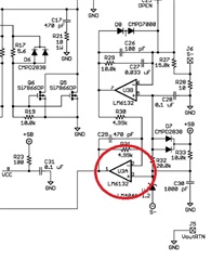
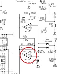
Hi Jerry,
Thanks for your reply.
Please see attached link.(LM5026-page26,LM5041-page14).
Best Regards,
I know “The schematic in page 14 of the LM5041 datasheet shows such a scheme.
U4A is the error amplifier. C35, R35, C36, R42, C40 and R32 make up the type III compensation network.”
reference attached link.
So,what is the role of U4B.
Hi Jerry,
Thanks for your reply.
Does the application circuit use Type2 + Type3 for feedback control circuit.
For example:LM5041 application circuit,Type2=U4B(LM6132) + Type3=U4A(LM6132),reference attached link,pls.
and then , I think I found the answer to the question...the feedback control circuit need C42 (reference attached link,page14.)?
I found LM5026 & LM5041's Datasheet does't describe the capacitor that provide U3(photocouple) bias volt.
Now,I try to uesd the circuit.Finally,It is can work.but load & line regulation over 5-10%.I will tune it again.
if you have any suggestion,tell me pls.
Hi Jerry,
like you said before. I think LM5026(U3A),LM5041(U4B) is the error amplifier to attenuate the high frequency noise.
I guess Datasheet's typical application circuit lost cap.but I'm not sure...
If you have any good idea let me know by email,pls.
I will click [This resolved my issue].Thanks your help.