This thread has been locked.

If you have a related question, please click the "Ask a related question" button in the top right corner. The newly created question will be automatically linked to this question.

BQ25895: Current detect design application check...

Part Number: BQ25895
Other Parts Discussed in Thread: TS3USB221

Dear Sir,

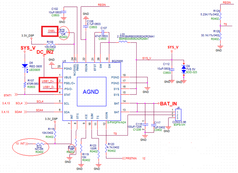
My customer wants to use D+/D- of BQ25895 to monitor and control the charging current.

The power source is from USB typeA port input and the test method as below.  

1. PC power on -> attached device and power on it -> charging from USB port with 500mA (customer think OK).

2. PC power on -> attached device and keep powered off -> charging from USB port with 1~1.5A (customer think it will have risk)

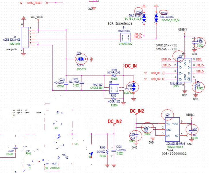
Customer now uses TS3USB221 and DSEL pin to control D+/D- while device powered on and off as below schematics.

IS this design OK to not?

Thanks.

  • Hi,

    1.D+/D- pins are used for USB input current limit detection when VBUS power is plugged in. During the charger input current limit detection process, the host must be able to HIZ D+/D- pins so that D+/D- pins are driven by the charger. If the host is unable to HIZ D+/D- pins, a USB switch is needed to isolate the host and the charger. The DSEL pin of the device can be used for D+/D- multiplexer selection control. Please refer to the EVM User’s guide at https://www.ti.com/lit/ug/sluuba2b/sluuba2b.pdf for sample circuitry.

    2. If the desired D+/D- input current detection result is 500mA, it is ok to leave D+ and D- pins open.

    Thanks,

    Ning.