Hi expert,
I found there's also CMTI definition here for such kind of isolated parts, except isolator and isolated gate driver.
As explained in this app note: Common Mode Transient Immunity (CMTI) for UCC2122x Isolated Gate Drivers
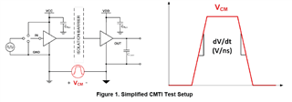
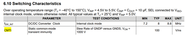
Common mode transient immunity (CMTI) is defined as the maximum tolerable rate of rise or fall of the common mode voltage applied between two isolated circuits. The unit is normally in kV/us or V/ns. High CMTI means that the two isolated circuits, both transmitter side and receiver side, function well within the datasheet specifications without error when striking the insulation barrier with very high rise (positive) slew rate, or high fall (negative) slew rate
High CMTI means when high dv/dt happens, the part still "function well". In digital isolator, this can be easily understood, as it's related to how primary side PWM signal is modulated and transferred to secondary side.
But how to understand CMTI for this kind of isolated power supply? How to define "function well" in test?