This thread has been locked.

If you have a related question, please click the "Ask a related question" button in the top right corner. The newly created question will be automatically linked to this question.

TPS61160: TPS61160 stops working after a powered up reset

Part Number: TPS61160

Hi Team,

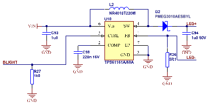
The circuit is the same as shown on the datasheet except Rset is 5R1 (current at 40mA).  The CTRL pin is connected to the micro and has a 10k pull down resistor.


The issue is that sometimes after a powered up reset from say, an Over the Air update, the TPS61160 stops working, let’s say locks up as there is no recover from it other than a full power cycle.


My question is what can we possibly be doing during the “warm” reset that could be locking up the TPS61160?  The power supply to the TPS61160 is not removed, the only thing is that during the “warm” uPC reset, over which we have no control, that the CTRL pin does something odd which upsets the TPS61160.


Any ideas? Thanks.

  • Hi hao

        Can you help clarify how you did the “over air update”. What is the operation condition before this update? The lockout faults are all given in the data sheet.

  • Hi Mason,

    The only lockout fault which I can find in the data sheet is an Undervoltage Lockout which is not happening and is also self-clearing. Would you please advise where these are in the data sheet?  The Datasheet I have is SLVS937C –MARCH 2009–REVISED JULY 2016 which I believe is the latest.

    By “over the air update” I mean we reprogram the microprocessor by sending new code over the internet.  Once the micro is reprogrammed it goes through a reset and at this time the TPS61160 “locks up”.  The supply voltage never changes, the only thing that can be happening is that something odd is happening to the control pin, as the uPC goes through its reset, but what can that be that effectively stops the TPS61160.  The PWM Control is definitely there after the reset but no output.


    Is it possible for something on the Control pin, an undefined voltage, an oscillating signal, maybe causes the Input Buffer to “latch up”?

  • hi hao

        thanks for your information. Also when you mentioned "a full power cycle" to restart the device, does it mean turning off and on the input voltage again? 

         Normally, there should not have lockout caused by Control Pin, can you help provide the waveform of both input voltage and ctrl pin voltage under the abnormal condition?

  • Hi Mason,


    12V picture attached,. AC coupled, 100mV / div, 500ms / div.  Once I get the trigger sorted, I will get the other picture.


    But just to clarify.  The power supply is 12VDC and varies by less than 100mV at any time.  The only other thing is that the PWM Signal going to the CNTL pin is an asynchronous reset, ie. we don’t know where in the cycle it maybe when the Reset Occurs.


    I agree with you re the lockout on the control pin, but it is either that or the Power Supply.


    Circuit for your reference. Thanks.


  • Hi Mason,

    I have looked at all the signals but can find nothing wrong. However, on further digging I came across App Note SLVA471 where I found this interesting piece of text.


    The TPS6116x family of devices allows dimming through the CTRL pin using two methods. The first is accomplished by applying a PWM signal to the CTRL pin which varies the reference voltage based on the duty cycle. This method is considered analog dimming because it applies a constant current through the LEDs rather than pulsing the full current. The main disadvantage with this method is that the frequency of the PWM signal has to be within the range of 5 kHz to 100 kHz. The second method of dimming through the CTRL pin is the one-wire digital interface which also changes the feedback voltage, but the device must be disabled between each write which may cause a perceptible flicker.


    There is no information I can find concerning “the one-wire digital interface”.  Is it possible that somehow, inadvertently, we can put the TPS6116x into a zero-output state? If so, that would explain the issue.

  • hello Hao

            Regarding you analysis on the one-wire digital interface, we do not have previous case to support it is yes or not.   

           I want to confirm that there is no abnormal waveform triggered for the Ctrl pin?

           Besides, I hope to get the clarification on the condition from you, so that I can have a test on EVM to see if this issue can be duplicated. Here is my understanding on the condition: 

           The issue happens after the SW update of MCU, during the update, Vin is still on. Then the device cannot start up, no output voltage and current. Only when Vin is on and off again, device can operate normally.  

  • Hi Mason,


    We cannot see anything we are doing to the chip during a microprocessor reset that is any different to what we do when we intentionally turn the backlighting off and back on.  Us turning the backlighting off and on never fails to restart the 61160 but the Reset often, not always, fails to restart the 61160.


    My question is this what can we be possibly doing to the chip that would cause the 61160 to “lock out” and not come back until the power is cycled?  You mentioned in one of your previous comments, “TI suggested that check the lockout faults which are all given in the data sheet”, can you please define what are these lock out faults as other than the UVLO I can find no others. 

  • Hi Mason,

    Firstly, let’s get rid of a little confusion, I discovered over the weekend there is a difference between the TPS61160 and 61160A.  The one wire interface only applies to the 61160 and not the 61160A. We are using the 61160A.


    As to abnormal waveform I can see nothing other than the PWM stopping when the RESET occurs and then restarts 200+ms after the processor is initialised and starts running.  I will continue to scope it and see if I can see anything I have missed.  If I have missed any thing it would a very short (under 1us) pulse.


    But what happens to the CNTL pin is no different to what occurs when we intentionally turn off and back on the backlight.


    Basically your understanding is correct.

  • hi Hao

        Actually, UVLO is not real "lock out" as it can be released as long as the voltage rises above the threshold.

        Thanks for your clarification. So according to your description, no difference is observed between REST and normal backlight on/off. What is the behavior of 200+ms, does the voltage at Ctrl pin keep low level?

  • Hi Mason,

    The only difference I can see between normal on/off and RESET is that the PWM (period 80us) is started with a pulse width of 300ns (approx. 80us / 255) whereas the on off is more likely to be somewhere between 25 and 75% mark/space ratio.


    One point not to forget, is that this chip “latches out” and only a repower will bring it back.  There is nothing in the datasheet that suggests that this is possible.


    Can a dip or spike on Vin cause it? 

    Can a pulse or pulses on the CTRL Pin cause it? 

    Can the CTRL pin work with an 80us period and a 300ns pulse?


    Further information.


    I have grounded the CTRL line, physically, during reset (which would eliminate the 300ns pulse) but it still occasionally stops.

    I have put a 15uF Tant across the 61160 supply but I did not fix it.

    I also put a 4700uF across the incoming 12V supply but again it didn’t fix it.


    One other point I should make is that different PCBs act differently, I have ones which will only fail occasionally and others that almost never work.


    Here is the layout of the PCB. PLEASE NOTE there is a complete ground plane on this layer and on the bottom layer and Schematic


  • hi Hao

      1. Is it available to attach the waveforms mentioned in your first paragraph?

      2. You are right. The latch-out that needs repower to bring it back is not clearly described. The device should be recovered when current or voltage is back to normal range, there is no need to repower.

     3. We had some information from another device that the sequence of power on Vin and applying PWM signal will have impact on the start-up of the device. Have you ever tried to apply input voltage first and then PWM signal? I guess most of the time PWM signal is given firstly and then the input voltage at your side.   

  • Hi Mason,

    Please see our comments below.

    Is it available to attach the waveforms as we discussed?

    Attached - File names are description PWM Stop and Restart thru Reset 1 and 2 are one failure and one OK and as you can see there is no obvious difference.

    You are right. The latch-out that needs repower to bring it back is not clearly described. The device should be recovered when current or voltage is back to normal range, there is no need to repower.

    Concur it should but doesn’t.

    TI AE had found some information from another device that the sequence of power on Vin and applying PWM signal will have impact on the start-up of the device. Have you ever tried to apply input voltage first and then PWM signal? I guess most of the time PWM signal is given firstly and then the input voltage at your side. 

    From Power up Supply is there first and 800ms later the PWM starts.  During RESET and On/Off Vin is never removed.

  • Hi Mason,

    2 More Pictures of switching wave form (Pin SW)

    SCR11 is higher brightness backlight and

    SCR12 is lower brightness.

  • hello Hao

           Thanks for the feedback.

    1. what does channel 1 represent in the first two waveforms?  is it 3V3power supply for MCU? I guess channel 2 is Ctrl pin voltage. And the second is the zoom in result of the first result. Waveform #1 & #2 reset, #3 PWM stop.

    2. What does channel 1 in last waveform represent? Is there any problem on start-up of the device under the operation of both two sequences? It seems the operation is ok for Vin first and then PWM sequence from the attached result. 

    3. To make it clear if anything odd on Ctrl pin, Is it available to break the connection of MCU and Ctrl pin before over-air update first, and keep other operation condition the same. After over-air update, reconnect MCU and Ctrl pin and see if everything is ok.

    4. please help clarify the input voltage, output voltage and inductance, not clearly given in the schematic. I will check the SW results you updated just now. CH1 is?

  • Hi Mason,

    I am not sure what you are asking me in the first two questions.


    Descriptions

    PWM Stop and Restart #1 and PWM Stop and Restart #2 are a good restart and a failed restart Channel 1 is RESET Pulse (Trigger point “T” on top)

    12 Supply at Reset shows 12v (AC Coupled @100mV/div)

    12 Supply at Reset Shows the same as above (@500mv) just over a longer time, backlighting would restart about 800ms after Reset (Channel 1 and trigger)

    PWM Stop at RESET shows PWM signal (Ch 2) and Reset (Ch 1)

    PWM Start shows the first 2 pulses that are on the CTRL pin after Reset (approx. 82us apart and of 320ns duration [82us / 255])


    3:            I have done that by connecting CTRL to ground and releasing it after processor restarts it still fails. Not every time but it does.


    4:            Vin 12VDC, Vout is about 16-17V (see Vpeak on SCR11/12), Inductor is 22uH, 432mΩ, Isat 800mA made by Taiyo Yuden.  I have a SRR4028-220Y Bourns Inductor arriving to swap just to be sure. (22uH, 185mΩ, Isat 720mA and shielded).  In SCR11/12 Ch1 is not connected.

  • hi Hao

       Thanks for the information, just confused about the intention that waveforms would like to present at the beginning. Now I get a understanding on this. So I guess right now we have a temporary conclusion that it is not the Ctrl pin causing failure according to the test mentioned in (3). 

       For the SW result, it seems the converter operates in DCM mode both in higher brightness or lower brightness, may I ask the LED current? 

       when you did the over-air update, normally what configuration of PWM will be updated? or Even update the same code, failure still happens.

       You mentioned different PCBs act differently, have you replaced the IC on good PCB board with the failure IC to see if the failure is really related to the layout?     

  • Hi Mason,

    For the SW result, it seems the converter operates in DCM mode both in higher brightness or lower brightness, may I ask the LED current? 


                                    40mA, from Data sheet

    3.1.3 Backlight driving conditions

    Voltage for LED Backlight VL -- 18.0 -- V Note 1

    Current for LED Backlight IL -- 40 -- mA

    LED life time -- -- 50000 -- H Note 2


    When you did the over-air update, normally what configuration of PWM will be updated? or Even update the same code, failure still happens.


                                    PWM Configuration does not change with firmware update.


    You mentioned different PCBs act differently, have you replaced the IC on good PCB board with the failure IC to see if the failure is really related to the layout? 


                                    So far, they all fail at some time just some are much more prone than others.  I’m not sure if I understand the comment about swapping ICs and layout as all PCBs have the same layout.

  • Hi Hao,

    Mason and our other experts on this issue recently started celebrating the Chinese New Year.  They will respond when they return the week of 2/7.

    -Jim

  • hi Hao

       Last time you mentioned "One other point I should make is that different PCBs act differently, I have ones which will only fail occasionally and others that almost never work." So when I have the comment about swapping ICs, I would like to know if this issue is only determined by PCB or specific IC. 

       Besides, I would like to confirm with you that no matter the sequence of Vin and PWM signal, the device can start up normally. 

  • Hi Mason,

    Not quite sure I understand what you mean, however let me describe what we do.


    Power up

    12V applied (that is also Vin)

    3V3 regulator starts

    uPC starts

    PWM Starts and ramps up

    This always works


    Display off/on

    All power supplies are on

    PWM switches off

    Display dark

    PWM starts

    Display lights

    Always OK


    Reset (using watchdog) after OTA update

    PWM stops (caused by watchdog)

    Vin has about a 100mV step in it as processor load drops comes back down as processor restarts, nothing more than 100mV on the 12V supply

    PWM restarts and ramps up

    NOT always successful


    Since then, we have come up with the following.


    After 2 days of trying lots of things, I think I've come up with a BL solution that works on the startup side. Watchdog every 8 seconds after reset and no fails. No idea why it works, just trial and error. It ramps the pwm and the BL to the highest level as soon as possible after reset and then drops it to 0 for 50ms before resetting/writing the display. You have to see a bright screen for a short while at powerup.


    I hope this helps and explains some things

  • hi Hao

        Please try this power up sequence:

    3V3 regulator starts

    uPC starts

    PWM Starts and ramps up

    apply 12V Vin 

        When you mentioned "Watchdog every 8 seconds after reset and no fails", does this mean the device can be power up normally by this action? 

        However, there is  bright screen for a short while at powerup. So the BL will always comes to highest level no matter what duty cycle of pwm is?

        What I want to know in last reply is that if this issue only happens for one or several ICs, not for all TPS61160 device. If so it would be better to do FA for these devices to see if there is any problem inside the device.

  • Hi Mason,

    Sorry, no can do, as the 12V Vin is where the 3V3 regulator gets its power from.

     What I want to know in last reply is that if this issue only happens for one or several ICs, not for all TPS61160 device. If so it would be better to do FA for these devices to see if there is any problem inside the device.

                  Not all devices act exactly the same some are much more likely to do it than others.

  • hi Hao

       Sorry for late reply due to business trip. 

       Then maybe you can go with your current solution by "Watchdog every 8 seconds after reset".  Honestly speaking, I cannot think of what difference this will cause to the LED driver, this action just keeps MCU active. If you have more concern and findings, feel free to discuss. thanks for your information again.