This thread has been locked.

If you have a related question, please click the "Ask a related question" button in the top right corner. The newly created question will be automatically linked to this question.

TPS25946: OverCurrent protection for linear actuators application. Several questions about eFuse design

Part Number: TPS25946

Hi. In my application, one actuator is moving a mechanism and this mechanism can find obstacles if there is a malfunction. I want to use this eFuse as an overcurrent protection, when the actuator hits this possible obstacle, the current will increase and it's when I want the eFuse to act, shutting down and sending a FLT signal to the MCU. That's why I want to use the specific part TPS259461LRPWR (latch and FLT pin). This actuator is moving a variable load so the current changes along the range of the linear actuator. The maximum current measured along this range is 1.6 A so I want to set the current limit to 2 A (due to tolerances). 

I'd need help to confirm and figure out the following parameters: 

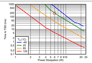
1) According to my measurements, when there is an obstacle and the current reaches 2.7 A (I'm choosing 2.7 A because it'd be a good point for the eFuse to act) , the voltage in the actuator is 12.1V, that gives me a resistance of 12.1/2.7 = 4.5 ohm. So the output voltage in the eFuse would be 2A * 4.5 ohm = 9V. That it's giving me a power dissipation of (12.1 V - 9V) * 2 A = 6.2 W. And according to the plot of the datasheet, it'd take around 200 ms for the eFuse to enter in the thermal shutdown (25 degrees): 

Please confirm me if this makes sense, taking into account my specific application. 

2) If I don't need to use the SPLYGD pin, can I leave it floating? 

3) In order to calculate the CdVdT value, the datasheet provides the following equations: 

"SR = Vin/tr" How can I know the ideal "tr" for my application? 

With that, I already can calculate the CdVdT value (CdVdT = 2000/SR) but in order to calculate the Inrush current, I need to know the Cout value (Iinrush = SR * Cout), how can I estimate the value of Cout? I don't only need to know this value for the Inrush current calculation but for the schematic too. 

4) As I've said, I want to use the FLT feature, so in order to do that, I need to pull up this pin to a digital voltage value (5V in my case) through the resistor Rflt. The problem is that my product works with a battery and I want to save as much current as possible. Can the value of this resistor be high so that the current in the FLT circuit is of the order of uA? 

Thank you very much in advance. 

  • Hi Alberto,

    Thanks for reaching out!

    1. Your calculation looks correct. Just one thing you calculated VOUT assuming load is resistive. If load is like dc-dc converter then you have to assume constant power load and then calculate VOUT.

    2. Yes you can leave SPLYGD open.

    3. Alberto ,  output cap is the total cap you have at output of eFuse that is close to VOUT pin. If you dont have specific TR time requirement then we can choose minimum  time that give successful startup. What is the load at output of eFuse, like is it a dc-dc converter ?

    4. Yes . You can try with 470K,1M

    Regards

    Kunal Goel

  • Hi Kunal, 

    Thank you very much for your answer. I really appreciate your help. 

    Regarding the point 1 and 3. In my PCB design, I have first a dc-dc converter and then this eFuse connected to the output of the dc-dc converter. At the output of the eFuse, I have a H-Bridge connected in order to control two linear actuators and at the output of the H-Bridge I have the two actuators so there is no voltage regulation downstream of the eFuse, only the H-bridge and the actuators. 

    Please let me know if you need more information. 

    Thank you again. 

    Regards

    Alberto. 

  • Hi Alberto,

    Actuator is like a dc motor , right? So I think we can assume it to be resistive as coil impedance will decide voltage . The H-bridge you will use doesn't have any input cap ? 

    What you can do is , keep placeholder in your schematic for cap at dvdt and while testing you can adjust that cap based on requirement.

    Regards

    Kunal Goel

  • Hi Kunal, 

    Yes, the actuator is a dc motor. Regarding the H-Bridge, I have to check if it has an input cap since it's an external PCB manufactured by another company. What would change if it had it or not? 

    Yeah, that's the best idea for the dVdT cap I think. What about the Cout cap? I guess this question is related to the above one.

    Thank you. 

    Regards,

    Alberto. 

  • Hi Alberto,

    The cap at input of your load will be output cap for eFuse. Based on cap at output of efuse , we will decide dvdt cap such that inrush current is acceptable and device powers up successfully.  Refer 9.2.2.3 Setting Output Voltage Rise Time (tR) for more info in www.ti.com/.../tps25946.pdf

    Regards

    Kunal Goel

  • Hi Kunal, 

    Got it. I think that I have everything to finish my design now. 

    Thank you so much for your help. 

    Regards,

    Alberto.