A related question is a question created from another question. When the related question is created, it will be automatically linked to the original question.
If you have a related question, please click the "Ask a related question" button in the top right corner. The newly created question will be automatically linked to this question.
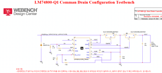
1. The FET selected is only 40V rated. If this is an Automotive application, we would recommend using at least 75V rated FETs are recommended along with SMBJ28A and SMBJ58A connected back-back at the input. For more understanding on this topic, please refer to '11.3 TVS Selection for 24-V Battery Systems' section of the datasheet.
2. With 110 kohms and 6 kohms resistor ladder on the EN/UVLO pin, the EN rising threshold = 23.79V and the EN falling threshold = 21.88V
With 110 kohms and 3.74 kohms resistor ladder on the OV pin, the OV rising threshold = 37.4V and the OV falling threshold = 34.36V