This thread has been locked.

If you have a related question, please click the "Ask a related question" button in the top right corner. The newly created question will be automatically linked to this question.

BQ76952: I2C communication is interrupted and the SDA pin is pulled low

Part Number: BQ76952

Hi team,

Here's an issue from the customer may need your help:

Customer-designed acquisition board for the BQ76952, after some time of I2C communication, the chip will pull down the SDA, resulting in an I2C communication interruption.

VG=43V when control of precharge MOS is on and VG=45v when is off. Why is VGS=-8v(total voltage 51v) when is on and VGV=0 when is off? The VGS theoretical value should be -6V at shutdown, why is the precharge MOS shutdown gate different for ground voltage, but the VGS=0.

Could you help check this case? Thanks.

Best Regards,

Cherry

  • Hello Cherry, 

    Can they describe better what their I2C communication issue is? A logic analyzer waveform of the issue would be useful.

    See Section 7.8 PCHG and PDSG FET Drive of the datasheet for the drive of the FETs. The FETON drive is ~8-V, which is the VGS that you see when the FET is on. When the FET is off, the VGS is ~0-V, so the part is working as intended.

    The issue you are experiencing is likely due to a voltage-divider effect when measuring to GND. The RGS resistance is recommended to be >1-MOhm, and I believe the one used in the EVM is 10-MOhm. With the standard meter/10x scope, when you measure to GND you have a 10-MOhm input resistance through the instrument, so you get a voltage divider between the RGS of the FET and  input resistance of the meter. Causing the voltage measured to be the voltage divider value.

    Albeit for a different part, we have a diagram showing a similar behavior in Figure 4-1 of SLUA774B.

    Best Regards,

    Luis Hernandez Salomon

  • Hello Luis,

    Thanks for your help!

    Can they describe better what their I2C communication issue is?

    The communication between the MCU and the AFE is interrupted after a period of operation, as verified by the oscilloscope, because the SDA of the AFE is pulled low to 0V. The normal frequency is 400k, and based on the I2C waveform from the evaluation board, the sampling frequency is found to be low. So the frequency is dropped down to 20k in the program, but communication will still be interrupted, and it's going to take a little bit longer.

    Now they send a request to the AFE every 100 ms and AFE600ms return data.

    Is this issue related to MCU or it's just the AFE issue? 

    Thanks and regards,

    Cherry

  • Hello Cherry,

    The issue is most likely from the MCU side or their I2C setup, it is also possible that it is due to their code. The BQ76952 should not pull the SDA signal low unless it is sending data in response to an I2C read.

    Can they upload a schematic on their I2C set-up? Could they try communicating using a different IC and see if they see the same issue? 

    Best Regards,

    Luis Hernandez Salomon

  • Hello Luis,

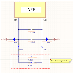
    Thanks for your response. Here's an additional question: why is the current sampling error 0.3 A? For example: the actual current is 5A, but the detected current value is jumping from 4.9A to 5.2A (load is a constant resistance). The shunt is connected in parallel with two 0.2 mΩ, removing two diodes, and detecting current runout within 0.3 A, which is still not eliminated. The circuit is as follows:

    Best Regards,

    Cherry

  • Hello Cherry,

    The capacitor values seem really high. We recommend a 0.1-pF capacitor (with optional 100-pF capacitor) placed between SRP and SRN, which we mention in Section 16.2 — Typical Applications of the datasheet. Additional capacitors from the pins to Vss can also be placed for further filtering (See Section 18.1 — Layout Guidelines in datasheet.)

    Fixing these values should fix your issue, there should be no reason current error is that high at that current.

    Best Regards,

    Luis Hernandez Salomon

  • Hello Luis,

    Thanks for your response!

    We recommend a 0.1-pF capacitor

    Mau I know how to get the 0.1-pF capacitor? The capacitance value on the evaluation board is 470uF, 220pF. If the sampling resistor is changed to 0.25 mΩ, does the capacitance need to be changed? Is there a formula? And is it the internal chip issue or is it determined by the sampling resistance?

    The main problem with I2C is that the I2C is stuck and the SDA is hung during communication. It dose related to the MCU. How to solve this problem to ensure I2C stability? The I2C for MCU hardware is applicable.

    Thanks and Best Regards,

    Cherry

  • Hello Cherry,

    The evaluation board very clearly shows 0.1-uF and 100-pF. They can see the schematic in Figure 5-9 of the BQ76952EVM User Guide. There is no 470-uF or 220-pF in the evaluation board.

    There is no formula, these are the values that were found to work best. I am not familiar as to how these were reached but it is likely from the design of the device. You shouldn't need to change the capacitance on these if you change the sense resistor.

    We cannot really say what's wrong with the MCU. There can be many reasons. They should check their I2C set-up to make sure everything is properly set. And check their code to ensure the timings are okay. They may see our MCU Programming with the BQ769x2 family training video, the BQ769x2 Software Development Guide and look at our example code found the Software Development section of the BQ76952's product page, for more guidance.

    Best Regards,

    Luis Hernandez Salomon

  • Hello Luis,

    Thanks for your support again!

    The evaluation board very clearly shows 0.1-uF and 100-pF. They can see the schematic in Figure 5-9 of the BQ76952EVM User Guide. There is no 470-uF or 220-pF in the evaluation board.

    There is no formula, these are the values that were found to work best. I am not familiar as to how these were reached but it is likely from the design of the device. You shouldn't need to change the capacitance on these if you change the sense resistor.

    Regarding the  capacitance of 100 pF, they have also tried  220pF and 22pF, but the current jump issue still remains. Is it related to the position of the capacitors, do these two capacitors need to be close to the pins?

    And here's also some additional questions:

    1. Why the voltage error of LD and PACK is large, the measured error is between 0.7-0.8 V, for example, LD measured 52.1 V, showing 51.38 V.

    2. Are there series resistors inside the equalizer circuit chip, and what is the resistance value?

    3. What is the impact of the floating FUSE pin on the chip function and whether it must be grounded?

    Thanks and Best Regards,

    Cherry

  • Hello Cherry,

    Looking deeper into it, the error in voltage may be due to the small sense resistance. The smaller the sensor resistor, the higher the error can be at lower currents. This is due to the coulomb counter accuracy. We detail the coulomb counter possible error in Section 7.15 — Coulomb Counter of the datasheet. This is a downside of choosing a smaller sense resistor to allow a higher current.

    With the datasheet's values, calculated an estimated typical error of ~0.5-A at 5-A going through a 0.1-mOhm sense resistor. The calculated error might not be exact as there are many factors that affect these values, but it may give a clue as to why you are seeing a 0.3-A error in the measurements.

    Try setting the userAmps settings to 10-mA and see if there's any change in the measurement.

    As for your questions:

    1. Why the voltage error of LD and PACK is large, the measured error is between 0.7-0.8 V, for example, LD measured 52.1 V, showing 51.38 V.
    LD and PACK must be calibrated by the user. It may be that these are uncalibrated.

    2. Are there series resistors inside the equalizer circuit chip, and what is the resistance value?
    I assume you are talking about the cell balancing circuit. Read our Cell Balancing application report. Typical internal cell resistance is ~25-Ohm.

    3. What is the impact of the floating FUSE pin on the chip function and whether it must be grounded?
    There is no impact, you can either leave it floating or pull it to ground. We mention this in Section 16.6 — Unused Pins of the datasheet.

    I hope this was helpful.

    Best Regards,

    Luis Hernandez Salomon

  • Cherry,

    I also forgot to mention, yes, the capacitors need to be placed as close as possible to the IC. Use 0.1-uF and the 100-pF recommended values.

    Best Regards,

    Luis Hernandez Salomon