A related question is a question created from another question. When the related question is created, it will be automatically linked to the original question.
If you have a related question, please click the "Ask a related question" button in the top right corner. The newly created question will be automatically linked to this question.
Part Number: TPS65217 Other Parts Discussed in Thread: USB2ANY,
Our customer bought TPS65217EVM, they followed all the jumpers.They did pump 3V3 and 5V into the evaluation board and still no output. Can anyone guide us how should they set for the evaluation board?"
Thanks for providing the information in the previous message! The scope capture that I requested before is important to evaluate the signals on the power path that supplies the PMIC rails. The output voltage from the converter can be excluded as there is no output voltage but AC, USB, SYS and PWR_EN are critical because they are input signals to the PMIC. If the customer could also provide a picture of their setup, that would be great.
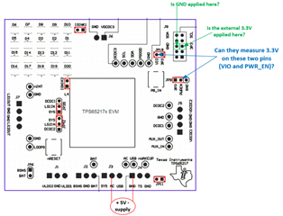
Since the USB2ANY is not used, I suspect the external 3.3V is probably not being applied to the right pin on the J8 connector. Can they try the suggestions below and let me know if they see any difference?
Apply the external 3.3V on the J8 connector and measure the voltage on the "3P3" pins on JP18 and JP9 to make sure the voltage is getting there.