


Hello,
I have a client that wants to power a device with battery voltages ranging from 3 V to 12 V. The required device voltage is 3-3.3 V, so we used the TLV2217-33. I designed the power circuit to have a battery plug-in that is regulated by the voltage regulator to 3.3 V, and then a separate battery input that powers the device directly at 3 V. There is a switch between the voltage regulator and higher-voltage battery. The schematic is shown below.
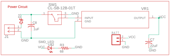
I realize there should be reverse voltage protection of the BATT battery, and something to avoid backdriving the BATT battery, but my client requested to leave those out. However, I'm not sure if I have designed the switch with the regulator correctly. It correctly turns off the battery before the voltage regulator to avoid power drain on the higher-voltage battery (J1) when the switch is disconnected. Assuming the switch is connected to the ground side and the 3V battery (BATT) is connected, what is the best way to avoid backdriving the voltage regulator? I grounded the input assuming it would power down the voltage regulator, but it got really hot when we tested it, which makes me think it backdrove the internal transistor.
I have two questions:
What happens when the voltage regulator is connected like this (3.3 V on output, input grounded)?
What is the best design to avoid backdriving the voltage regulator?
Thanks in advance,
Jarom

