This thread has been locked.

If you have a related question, please click the "Ask a related question" button in the top right corner. The newly created question will be automatically linked to this question.

TPS7H1101A-SP: 2 LDO's In Parallel Stability/Bode Simulation

Part Number: TPS7H1101A-SP

Which if any of the PSpice models (WCA or Transient) support stability/bode plot simulations of 2 LDO’s operating in parallel?  If none, is there a way to do a stability/bode plot simulation using a single LDO that would be a good approximation of 2 LDO’s operating in parallel?

Some observations:

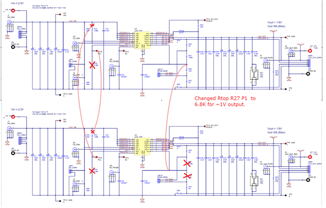
  • The WCA model seems to be the model prescribed for stability/bode plot simulations but doesn’t appear to have the provisions to support parallel functionality, i.e. no PCL nor CS pins.
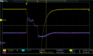
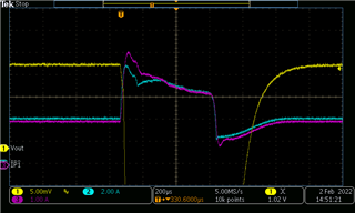
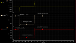
  • There is a test-bench in the transient model (Schematic=AC1, Sim Profile=AC-Bode) but when run the simulation profile that comes with test-bench and bode plot template placed at VOUT get anomalous results, see screen shot below. 

Please advise, Thank you -John

  • John,

    You are correct.  The model was not intended for this, and it was modeled/validated as a single device without current limit or sensing in the model.

    I am uncertain on the best approach to simulate the frequency response of multiple LDOs in parallel.  

    I am going to consult with the designer, and see if I can get some idea or insight on anything helpful.

    I will post back when I have an update.  Should be within a couple days.

    Regards,

    Wade

  • Thanks Wade,

       The loads powered have very tight tolerance and noise requirements with large current transients so we'll  need Cout much larger than the 220uF max guideline in the datasheet.  Consequently, very important we can simulate gain & phase margin with large Cout.  The power subsystem is on our programs critical path so you & your teams prompt attention to this issue is greatly appreciated.

    Thanks again Wade, -John

  • John,

    Thank you for the added information.

    On the surface, there is not a simple solution to evaluate this configuration.  However, the design team is going to take an in-depth look and make suggestions.   Forecast is having something back to you end of this week or early next week.

    Appreciate your patience.

    Regards,

    Wade

  • John,

    I wanted to give you an update.  We had to restore the design database, so we took a little bit of delay on this.   We are on track to test out a configuration on Tuesday, as Monday is a holiday.   Should be able to provide some additional information after our testing.

    Regards,

    Wade

  • Thanks Wade,

       I'll jump on this as soon as you follow up.  Inadvertently hit the resolved button, can you mark this back to unresolved for me, don't see a way to do that.

    -John

  • I don't think I have that capability.  However, by you replying to it, it will stay open.  It still will show resolved, but since it is open, it will still show up as needing attention.  So it should be good and will not be lost.

    Regards,

    Wade

  • John,

    We were able to get our simulations to run, and have verified in simulation operation 2 LDOs current sharing.  We are planning on testing this in hardware if possible.  Unfortunately, next opportunity to test is this Friday due to other constraints.

    I will reply back with results.

    Regards,

    Wade

  • John,

    Some good news/bad news.

    Good news is that the stability in simulation with the design database shows similar results to a single LDO with 1/2 the current.   We are working to validate this in hardware by modifying several of our EVMs.

    Bad news, is that it is going to take longer to validate this in hardware.  

    Currently I am planning on using 1.8V vout.   There is some opportunity to alter this if you provide the conditions you are using.

    By default, I will use 2x the EVM capacitance.  Each board will have 1-220uF, 2-3.3uF, and 1-0.1uF.   Approx 450uF on Vout.

    You indicated you will be using much larger than 220uF.  Do you have an estimate for your Cout?

    Regards,

    Wade

  • Thanks for the update Wade, our conditions:

        Vout=1.0V, Cout=1,240uF combined across the 2 LDO's (470uF + 150uF on each individual LDO)

    1,240uF was determined by limiting Vtran to 10mV with 1.9A Itran using Ic=C[dV/dT]=>C=(Ic)[dT/dV], and rounding up to standard cap values.

    dT used is 6us, consistent with Vtran shown in datasheet scope shots, & Fco ~=170kHz of bode plot of WCA model as downloaded from TI website with Cout=220uF.

    Concerned that with increased Cout, not only will stability be impacted but Fco will decrease, & dT (LDO response time) will increase, so there'll be a trade between increasing Cout, response time, & Vtran.    Huge value in accurate sim model to iterate through cases and converge on solution.

    Thanks again Wade,

    -John


  • Thanks John.

    I will see what I can do with getting close to your conditions.

    Regards,

    Wade

  • John,

    I have finished my initial hardware evaluation.

    I was able to test with a crude transient test when operating with about 3.8A (each LDO  just under 2A). 

    In this test, a brief mechanical short was added and released, and the recovery can be seen.  Fairly well damped response.

    In this plot, the Cyan trace represents current from both LDOs.  The purple trace is LDO1.  Note, the different scale for each.   Channel 1 has a 1V offset.

    The boards did not have as much capacitance as your design.    Each board had 1-220uF, and 2- 3.3uF for Cout.  

    I can see if I can find some larger tantalums to place on this to get this closer to your capacitance if this would be beneficial.

    The setup has ~6in cross coupled wires for CS to PCL connections and the feedback to the second LDO, so this is not necessarily very clean.

    I attempted to run a non invasion stability check with the parallel combination, but the results did not make sense.

    Regards,

    Wade

  • Thanks Wade, have a few follow up questions & polite requests:

    1.) Are the waveforms measured consistent with the database simulations performed, i.e. the waveforms measured are consistent with the simulation of a single ldo with ½ the output current used in the test?

    2.) What output current resulted from introducing the mechanical short, was it a "dead-short" that put part into current limit, if yes what is that current?  Looks like paralleled output goes up to ~8amps then resolves to ~6amps, not sure I'm understanding what was done?

    4.) The evaluation board looks to have a 50 ohm "injection-resistor" (R25) to support stability testing & bode plot generation, can stability testing & bode plot generation be done using that resistor for both single ldo operation and dual parallel ldo operation?

    3.) If possible please try additional testing approximating to the best you can output capacitance on each of the LDO’s:

            470uF, ESR=5milliohms + 150uF, ESR=6milliohms, for 1,240uF across the two LDO's.   I’m very concerned the total capacitance, & ESR of the testing will not produce representative behavior of our application.  Let me know if you'd like me to post mfgr part numbers for the caps, (provided that's ok on e2e).

    4.) Also, is it possible to do the tests using a single evaluation board by populating the backside ldo, concerned the added inductance of wires between the evaluation boards will not yield representative results to our application.

    BTW, I do have additional questions Re: setting output current limit and enabling current fold-back in parallel operation, I’ll be submitting new e2e post for this.

       Thanks again Wade,

    -John

  • John, I will attempt to answer all your questions.

    1) I have not seen transient sims yet.   I will confer with designer.

    2) The peak current is likely due to capacitance discharge, then the follow on current is limited by combination of source supply through the LDO, and potentially one or both LDOs current limiting as well.  The source supply's capability was around 7A.

    3)(4) The evaluation board does have injection resistor, but it is not correctly placed.   A spin of this board is planned to resolve this.  To get valid stability checks with a parallel configuration, it will be necessary to create a board designed for current sharing with stability hooks.   This is currently not planned.

    4)(3) I will see what I can locate.  No issue with you posting your part number from our perspective.

    5)(4) No, this will not work.  The footprints are 100% in parallel.  No way to cross connect PCL/CS with resistance.

    Regards,

    Wade

  • Thanks Wade,

    470uF: Kemet, T541X477M006AH**30 (** is surge option, any will do for testing)
    150uF: Kemet, T541D157M010AH**20 (** is surge option, any will do for testing)

  • Thanks John.

    I will see what I can locate that may be similar.  

    Regards,

    Wade

  • John,

    I have some additional feedback.

    I was not able to locate any of the larger tantalums locally.  However, I combined 3 220uF on each board.  This should somewhat resemble your total capacitance.  I have 6-T543X227M016ATE035.

    The transient response looked very well damped, and no oscillation.

    This was the same method, with a brief mechanical short.

    Additionally our design team simulated with your conditions.

    This plot shows simulated transient response in your configuration with a 2A to 4A and back with 500ns rise/fall.

    Regards,

    Wade

  • Thanks Wade, promising results.  I need to do an analysis of the pdn network between our loads and the bulk dcaps at ldo outputs to assess if the 500ns rise/fall time is reasonable approximation of our application. I'll follow up when i get that answer.

    While that's in process have some clarifying & confirming questions: 

        1.) Did both the simulation & lab testing include 2xLDO's in parallel with ~3.74k between LDO2:CS to LDO1:PCL & LDO1:CS to LDO2:PCL with no resistors from CS to Vin nor PCL to ground?

    2.) Did the simulation use the PSpice model for the "A" part on the website (not WCA nor "Non-A" transient model), if not what model was used and can I get that model?

    3.) I take it from the lack of a bode plot in this thread a model does not exist for frequency response simulation of 2 ldo's in parallel, i.e can't generate bode plot for gain & phase margin assessment of 2 LDO's in parallel, correct?  Therefore must rely on presence or absence of oscillations in transient model simulation for assessing stability, correct?

    -John

  • Yes, I agree the results are promising.

    1)   Yes, except the resistance between CS and PCL was 3.65K, as it was already on the EVM.  Here is markup of the schematic.

    Simulation setup to match.

    2) Simulation used transistor model extracted from the design database.   This model is not available outside of TI.

    3) I am not certain what level of stability check can be performed in the design database with 2 LDOs in parallel.  I will follow up with this.   However, transient observations of the hardware so far is the best assessment available.    I did attempt a non-invasive stability check, but the results were not valid.  Possibly because of the cabling between the two boards with additional parasitics.

    Regards,

    Wade

  • Thanks Wade,

       Accounting for spreading inductance through our pdn looks like the 500ns is reasonable rise/fall for current transient seen at the bulk caps at the ldo output.  Yes, please follow up with what if any stability checks can be done on design database, expect that'll close out this thread.

    As I mentioned previously I'll be submitting new post Re: Current limit & fold-back enabling in parallel operation.

  • John,

    Good news.  Was able to get stability sims run on the transistor model. 

    The simulations used mis-matching with process between the two LDOs.

    Transient sims were performed with a 2A load stepping to 4A (shared).

    Bode plots were run with 4A shared load.   For the bode plots: PM ranged from 54 to 73 degrees.   Fc ranged from 57-100kHz.  GM was approx 33 to 37 db.

    Granted, this is not in real hardware.  However, this data along with good transient performance on less than ideal hardware should provide some confidence in ability to achieve a viable solution.

    I don't have your answer for the question you have yet to post regarding current limit, but getting a head start on it. 

    I believe this should close this post out.

    If you agree, please click "This Resolved My Issue"
    Regards,
    Wade