This thread has been locked.

If you have a related question, please click the "Ask a related question" button in the top right corner. The newly created question will be automatically linked to this question.

TPS61022: Schematic review

Part Number: TPS61022

Dear team

There is a good news that we design in TPS61022 in customer's new project.

spec : Vin=0.8V~4.2V、Vo=3.74V

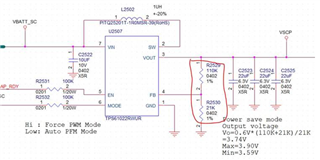
Could you help to review the schematic?

Many thanks

Denny

  • Hi Denny,

    That is great to know. Thank you for promotion. Could you please kindly share me with their output current requirement? Here is some comments from me:

    1.The voltage dividers R2529 and R2530's resistance is too low and this can increase effective quiescent current. Why does customer choose this?

    2.It is recommended to add a R-C in parallel with R2529 as feedforward compensation. You can just add place holder.

    3.What is the P/N of input and output capacitors. I want to know the effective capacitance under 3.74V DC biased;

    4.What is the initial EN and MODE status? It is not recommended to leave it floating (high impedance)

    5.What is the P/N of the inductor?

    -Wenhao

  • Hi Wenhao

    Thanks for your suggestions.

    The output current is about 1A~1.5A.

    1. The voltage dividers R2529 and R2530's resistance is too low and this can increase effective quiescent current.

    Do you have suggest FB resistance range for 3.74V vout

    2. It is recommended to add a R-C in parallel with R2529 as feedforward compensation. You can just add place holder.

    ok, we will reserve R-C to parallel with R2529

    3. What is the P/N of input and output capacitors. I want to know the effective capacitance under 3.74V DC biased;

    Input caps is GRM155R61A106ME11D, output caps is GRM158R60J226ME01

    4. What is the initial EN and MODE status? It is not recommended to leave it floating (high impedance)

    The EN will be control by GPIO, the mode pin is pull-up to VIN.

    5. What is the P/N of the inductor?

    Inductor is HTTP25201T-1R0MSR


    Many thanks

    Denny

  • Hi Denny,

    Please see my comments to the specs.

    The output current is about 1A~1.5A.

    [WW]With output to be 3.74V/1.5A, TPS61022 can probably reach to current limit when Vin is 0.8V.  Assume efficiency to be 65%. With input voltage=0.8V, input current needed is 10.8A, which exceeds TPS61022's current limit. The minimum input TPS61022 can go is about 1.2V.

    Do you have suggest FB resistance range for 3.74V vout

    [WW]EVM uses 100k for low side resistor. for 3.74V, you can use resistance near 523k for R1. If customer wants to further decrease Iq, they can use higher R2. However, considering they have already used FPWM, I assume they do not care about Iq because FPWM is not optimized for light load efficiency.

    Input caps is GRM155R61A106ME11D, output caps is GRM158R60J226ME01

    [WW]Input effective capacitance is not good. I would recommend add one extra input cap, like 3*GRM155R61A106ME11D. For such a high output current with low input voltage, output capacitance is not enough. Please consider to use >500uF/<10mOhm Electrolytic capacitor to make loop stable.

    Please use Calculation tool for detailed calculation process.

    You can find how to design output capacitor and CFF/RFF for such an application in this app note.

    The EN will be control by GPIO, the mode pin is pull-up to VIN.

    [WW]What is the default status of EN if GPIO is not working?

    Inductor is HTTP25201T-1R0MSR

    Inductor's saturation current and current rating is too small. Consider to use ISAT>12A. XAL7030-102MEB is an example.

    -Wenhao