This thread has been locked.

If you have a related question, please click the "Ask a related question" button in the top right corner. The newly created question will be automatically linked to this question.

BQ25570: only half charging with LiFePO4

Part Number: BQ25570


We're using the BQ25570 to charge a 3.2V LiFePO4 4000mAh battery in a pure harvest charger only scenario and have ROV1 and ROV2 configured with VBAT_OV set to 3.6V using the work spreadsheet. Our solar panel produces up to 7V so we're using a 4.2V low-loss voltage regulator to ensure the BQ25570 doesn't get a higher voltage than its rated maximum. For testing purposes we're using a 4.2V 500mA bench supply source with low impedance.

The battery charges from its uncharged 2.999V minimum up to about 3.3V, not an expected value closer to 3.6V, and then stays there in a steady state. Removing the battery and placing it in our constant current discharge setup circuit it only delivers about half the capacity vs an external LiFePO4 charger. Any idea why the battery is only charging about 50% of its rated capacity? We have a differently configured board with ROV1/ROV2 for a regular 4.2V LiPoly battery and it full charges to 100% with the 4.2V voltage regulator on the solar panel input without issue.

What should we set for VIN_DC and VREF_SAMP to calculate ROC1 and ROC2 in a constant 4.2V voltage regulated solar input scenario?

Thanks!

  • Hi Gavin,

    The BQ25570 is a boost only charger so VIN_DC (or VMPP actually) needs to be slightly less than 3.6V for it work as designed.  In your config, it is likely not boosting and simply connecting VIN_DC to VBAT through the high side FET body diode which gives a ~-0.4V-0.8V voltage drop.  However, I would have expected the battery to reach higher than 3.3V, unless the PFET between VSTOR and VBAT is turned off, which would add a second body diode voltage drop.

    Regards,

    Jeff

  • Thanks for the response Jeff! So in order to fully harvest charge a 1S LiFePO4 battery the solar panel needs to have VIN_DC regulated to something like 3.5V? And in a similar theme a typical 4.2V LiPo needs VIN_DC to be around 4.1V? We're not using the VOUT capability, is it best to disable the buck controller in our design by simply grounding VOUT_EN? What would cause the PFET between VSTOR and VBAT to turn off? 

    Would increasing VBAT_OV to a value such as 3.7V and having VIN_DC regulated to 3.6V provide full charging ability? In this VIN_DC regulated scenario, what should we plug into the spreadsheet for VIN_DC and VREF_SAMP so we derived proper values for ROC1 and ROC2?

    Gratefully Gavin!

  • Hi Gavin,

    The maxed spec'd VIN_DC to VBAT_OV is 200mV but I have seen 100mV work properly.  If you don't need the PFET between VSTOR and VBAT to provide undervoltage protection if the battery drops down to 2.0V, then you can simply short VSTOR=VBAT.  

    If VIN_DC <VBAT_OV then you can set VBAT_OV = 3.6V and get full charge.  The VIN_DC is normally the solar panel's open circuit voltage VOC. For you, it would be the output voltage of the linear regulator.  VREF_SAMP would be 80% x VOC if connected directly to a panel.  Since the output of the linear regulator is not a high Z source, you don't really need the MPP circuit, unless the regulator is collapsing the panel.  So, I recommend setting MPP=VREF_SAMP to 100mV or so below the linear regulator output.

    Regards,

    Jeff

  • Hi Jeff,

    I changed all of the resistor values and ensuring VIN_DC is less than VBAT_OV, but I'm still finding the circuit is only charging the LiFePO4 battery to around 3.3V and holding steady. The battery, after being charged with the BQ25570, with a known constant current drain only exhibits 50% the capacity of an external LiFePO4 charger's charge. My values are:

    VBAT_OV = 3.75, ROV1 = 5.76M, ROV2 = 6.19M

    VIN_DC 3.6V, VREF_SAMP = 3.5V, ROC1 = 5.49M, ROC2 = 442k

    Voltage regulator for VIN_DC producing 3.599V

    Any ideas?

    Thanks! Gavin

  • Hi Gavin,

    Is the BQ25570 boost converter still switching when VIN_DC=3.6V and VBAT_OV=3.3V?  Can you send a scope shot with VINDC, LBOOT and VSTOR like the one below? You can leave off the inductor current.  And then also a plot of VRDIV like below?  Note that your VRDIV plot will have a second for VOUT not shown below.

    Regards,

    Jeff

  • Thanks Jeff, I'll get those screenshots for you. How can I tell if the boost converter is still switching, from the traces you're requesting? Can you send a higher resolution image, I can't quite make out the VRDIV plot.

    Thanks!

    Gavin

  • Hi Gavin,

    Those figures are from the datasheet in the applications section toward the end.  The green LBOOST trace has squarish pulses like shown in figure 28 if it is switching.

    Regards,

    Jeff 

  • Hi Jeff,

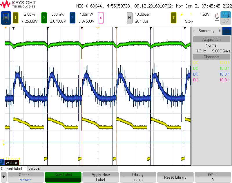
    Please find attached the scope traces you requested,

    Thanks, Gavin

  • Hi Gavin,

    On the top plot, is the yellow supposed to be LBOOST pin?  If so, it looks wrong.  It should be rectangular pulses like the green plots in figure 26.

    On the bottom plot, the second pulse should be 2/3 of the VBAT_OV setting and the third pulse is the VOUT regulation point.  That appears correct, yes?

    Regards,

    Jeff