This thread has been locked.

If you have a related question, please click the "Ask a related question" button in the top right corner. The newly created question will be automatically linked to this question.

LM5039: LM5039 Current Sense discussion

Part Number: LM5039
Other Parts Discussed in Thread: PMP10110

Hi Team,

There is a good new that we could DIN LM5039

And two questions need you confirm , thanks

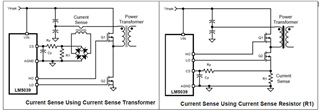
<1> Will the following two groups of practices make any significant difference to the LM5039?!
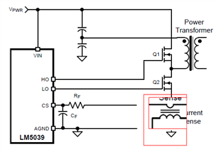
<2>If CT (current transformer) is used on the lower arm (indicating something like the red box below)... Would you recommend this approach?!
  • Hi Cheng

    Thank you for connecting. I will reply to you later.

  • Hi Cheng,

    In the datasheet of LM5039, the two methods can be employed in sensing the primary current. If using resistor to sense current, you need to care about the restart time and the value of the RES capacitor can be reduced to decrease the time before restart cycle is initiated. When using the resistor current sense method, an imbalance in the input capacitor voltages may develop when operating in peak cycle-by-cycle current limiting mode. If the imbalance persists for an extended period, excessive currents in the non-sensed MOSFET, and possible transformer saturation may result. This condition is inherent to the half-bridge topology operated with peak cycle-by-cycle current limiting and is compounded by only sensing in one leg of the half-bridge circuit. It is recommended to activate average current limit circuitry in such a configuration. However, since only alternative cycles source current into the ACL capacitor, ACL capacitor needs to be halved. This could still lead to a slight imbalance depending upon the input/output voltage levels and the impedance mismatch between the two phases of the half-bridge due to the additional CS resistor in the bottom half.

    So I think you can recommend customer to use CT to sense current of high side and low side MOS to avoid the possible imbalanced issue.

    BR

    Jerry Xu

  • Hi Jerry

    Thanks for your assistance....
    For the ACL...one more thing need your confirm!!
    LM5039 spec p25 in the reference circuit (red box) as shown in the figure below, and a resistor R24 parrall with C39 is there for ACL.

    What is R24 function? How to design the resistance value? THX

  • R24 is not used in the schematic.

  • Hi Jerry

    1.For the ACL...one more thing need your confirm!!
    LM5039 spec p25 in the reference circuit (red box) as shown in the figure below, and a resistor R24 parrall with C39 is there for ACL.

    What is R24 function? How to design the resistance value? THX

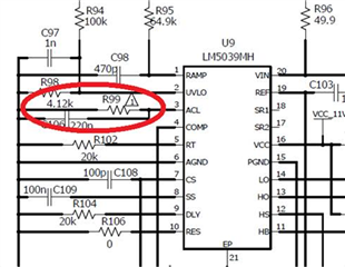
    2.In the reference design of PMP10110 (red box as shown below)

    Is there reason for R99 to install 4.12K?! Thank you.