This thread has been locked.

If you have a related question, please click the "Ask a related question" button in the top right corner. The newly created question will be automatically linked to this question.

UCC27282: BST capacitor simulation in TINA-TI

Part Number: UCC27282
Other Parts Discussed in Thread: CSD19535KTT

Hi Gate driver folks,

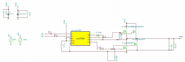
I'm proceeding a tina simulation with UCC27282 and CSD19535KTT. Would you 
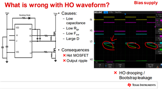
(1) BST capacitor

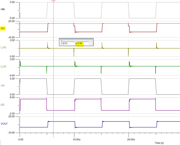
 Per page 8 in this material, I expect the HO shows dropping with the small (wrongly selected) BST capacitor. I believe 100~470nF would be proper, but the simulation still works with 10nF of BST capacitor! Even without dropping! The simulation also works with 10uF of BST capacitor! I guess it's not like to happen in bench. Could you advise on its operation? Is the tina simulation wrong? 

I want to check the operation of UCC27282 with external circuitry such as gate series resistor, gate input filter, etc.). If the tina model is wrong, do you not recommend to use this tina simulation?

UCC27282_BSTCap.TSC

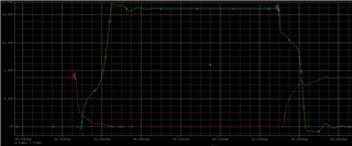
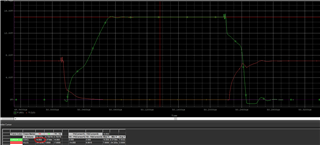
- C_BST = 10nF --> HO = 15.68V

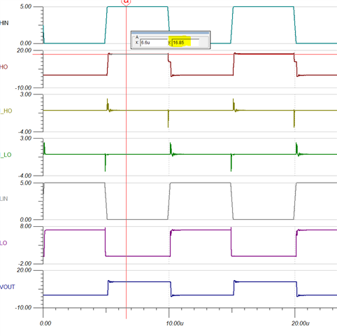
- C_BST = 100nF --> HO = 16.85V

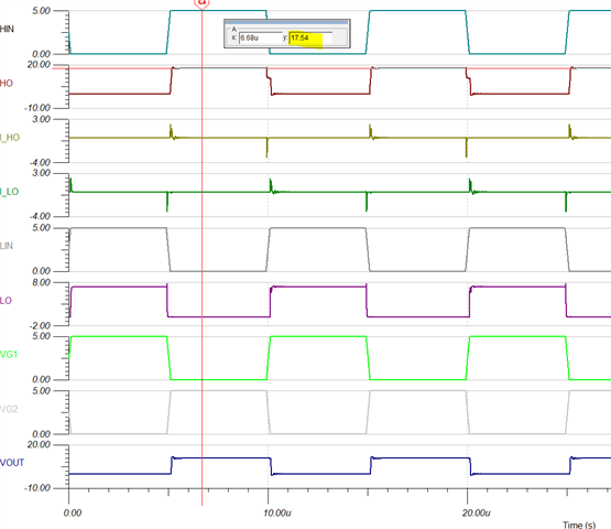
- C_BST = 10uF --> HO = 17.54V

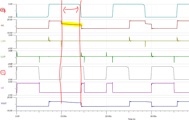
(2) Interlock function

I also want to check the interlock functionality of UCC27282. I set HIN with 70kHz and LIN with 100kHz. During the overlap period (that I marked with red arrow), HO is not fully turned off. Is it what really happen with UCC27282? Could you explain how this waveform appears?

UCC27282_interlock.TSC

Thank a lot!

  • Hi Ella, 

    Regarding your 1st question, based on the FET you are using and the parameters provided, 10nF does seem too low for the application since you would start seeing drop on the high side switch bias. As you mentioned, 100nF or higher would be the cap needed to keep the HB voltage above the UVLO level at all times. You may want to simulate this in PSpice to get a comparison, or to test it on an EVM (https://www.ti.com/tool/UCC27282EVM-335). As far as using 10uF, a too large bootstrap capacitor will take a long time to charge and will require longer low side on time. 

    Regarding your 2nd question, I think what you are measuring at the HO is with respect to GND, so what you are seeing during those periods is the voltage on HS pin w.r.t. GND. What you need to measure is HO with respect to HS (the voltage from gate to source of the top FET). This HO-HS voltage will go LOW (to zero volts) when there is input overlap and therefore the high side FET will turn OFF. 

    Best regards,

    Leslie

  • Hi Leslie, 

    Thank you for quick feedback.

    Regarding your 1st comment, I just want to be certain about the usual HO waveform with the low BST capacitor. Per my understanding, in the real world, HO waveform should be falling like the capture below, if it's a half bridge topology regardless of P/N. But it's strange that the initial high voltage (15.68V) is not discharged and keeps its value to stay in tina simulation. Is my understanding correct?

  • +

    I checked the operation in Pspice. The HO waveform is same with 15.64V - not drooping(CBST 10nF). 

    14.85V - not drooping(CBST 1nF)

    Which waveform is correct between the simulation or application note (what I captured in the previous reply)?

  • Hi Ella,

    Your understanding is correct. The bootstrap capacitor will discharge when HO is high (and LO is low) since it is providing the bias for the high side switch, and then it will recharge when HO is low and LO is high. If the capacitor is too small or the time HO is ON is too long then you'll start to see the HB voltage (and therefore the HO voltage) dropping significantly and potentially going below UVLO, such as the case on the slide you shared. If the bootstrap cap is sized correctly following the guidelines on the UCC27282 datasheet, then each cycle the cap will discharge very little within the allowable range.

    Best regards, 

    Leslie